Boring tool

a tool and tool body technology, applied in the field of tooling, can solve the problems of less robustness and simpleness of the tooling tool, and achieve the effect of small space and high accuracy

Active Publication Date: 2021-08-31
SANDVIK INTELLECTUAL PROPERTY AB
View PDF28 Cites 0 Cited by
  • Summary
  • Abstract
  • Description
  • Claims
  • Application Information

AI Technical Summary

Benefits of technology

[0014]By arranging the motor member inside the tool body together with the slider member in a cutting part of the tool body at the front end of the tool body and in parallel with the transversal extension of the slider member along said path the arrangement of the motor member and slider member inside the tool body may be very compact while still providing for a possibility of substantial adjustments of the radius to be created in a hole of a work piece when bored by rotation of the tool body. That the motor member is arranged in parallel with said transversal extension means here along and beside this transversal extension and the motor may also have parts coinciding with said path, for instance by an arrangement of the motor member coaxially with respect to a theoretical axis defining said path. Such an arrangement of the motor member with respect to the slider member enables considerable movements of the slider member along said path in spite of the fact that the motor member is arranged inside the tool body and in the cutting part of the tool body.
[0025]According to an embodiment of the invention the motor member is configured to drive a part thereof to rotate around a rotation axis extending in parallel with said path. Such an arrangement of the motor member makes it easy to transmit movements from movable parts thereof to the slider member, which may through an embodiment of the invention be obtained by configuring the motor member to rotate a gear in engagement with another gear so as to rotate a threaded member in engagement with another threaded member, in which one of these threaded members is connected to the slider member so as to cause movement of the slider member along said path by rotation of said gears.

Problems solved by technology

An adjustability of said boring radius by more than 60% would result in a need of complicated transmissions and / or designs of members connecting the motor member to the slider member making the boring tool less simple and robust.

Method used


Image

  • Boring tool
  • Boring tool
  • Boring tool

Examples


Embodiment Construction

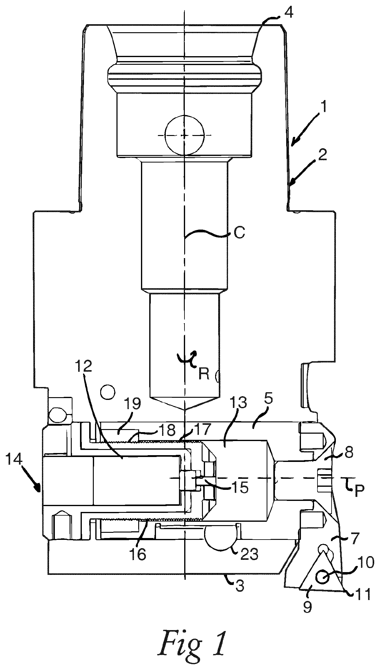
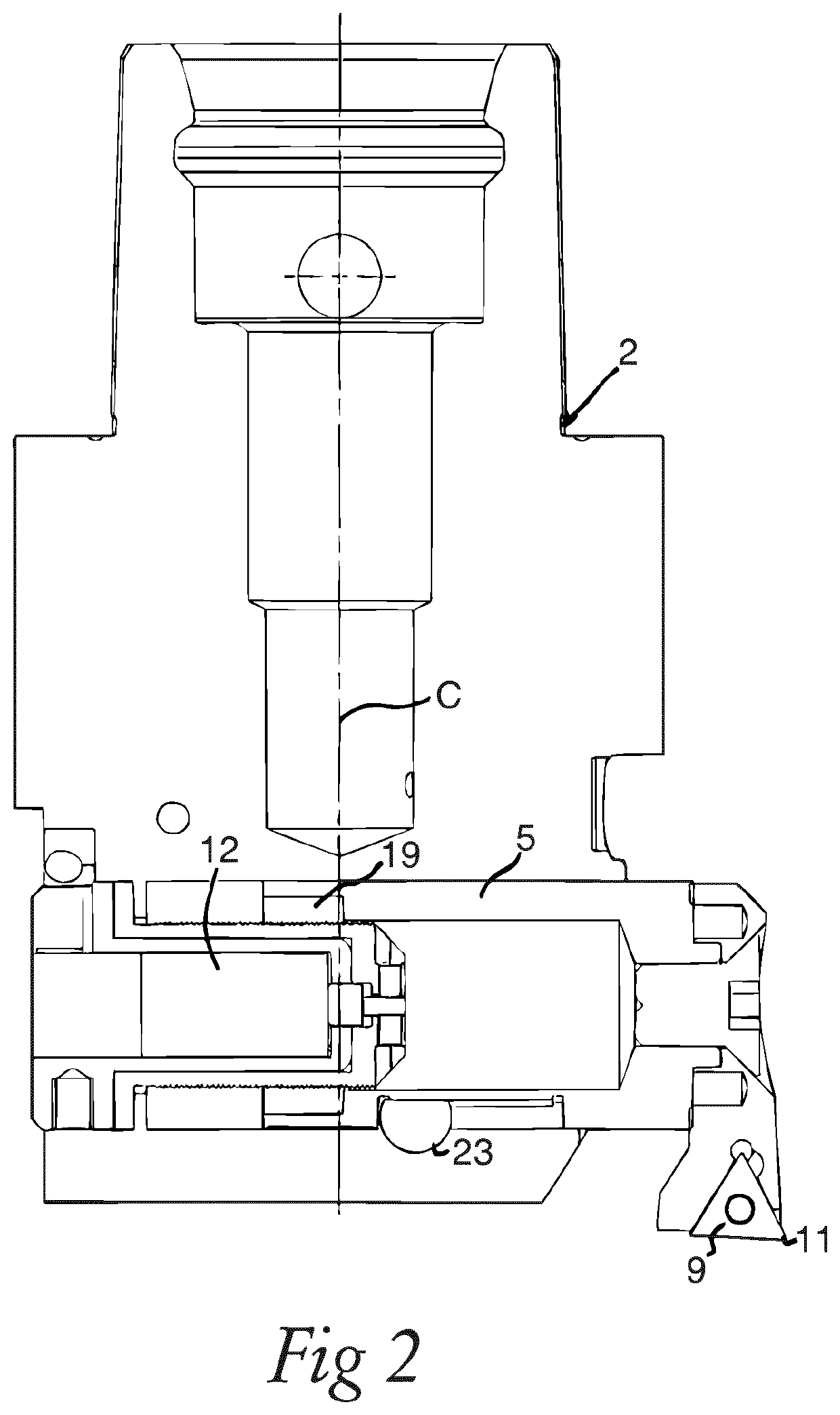
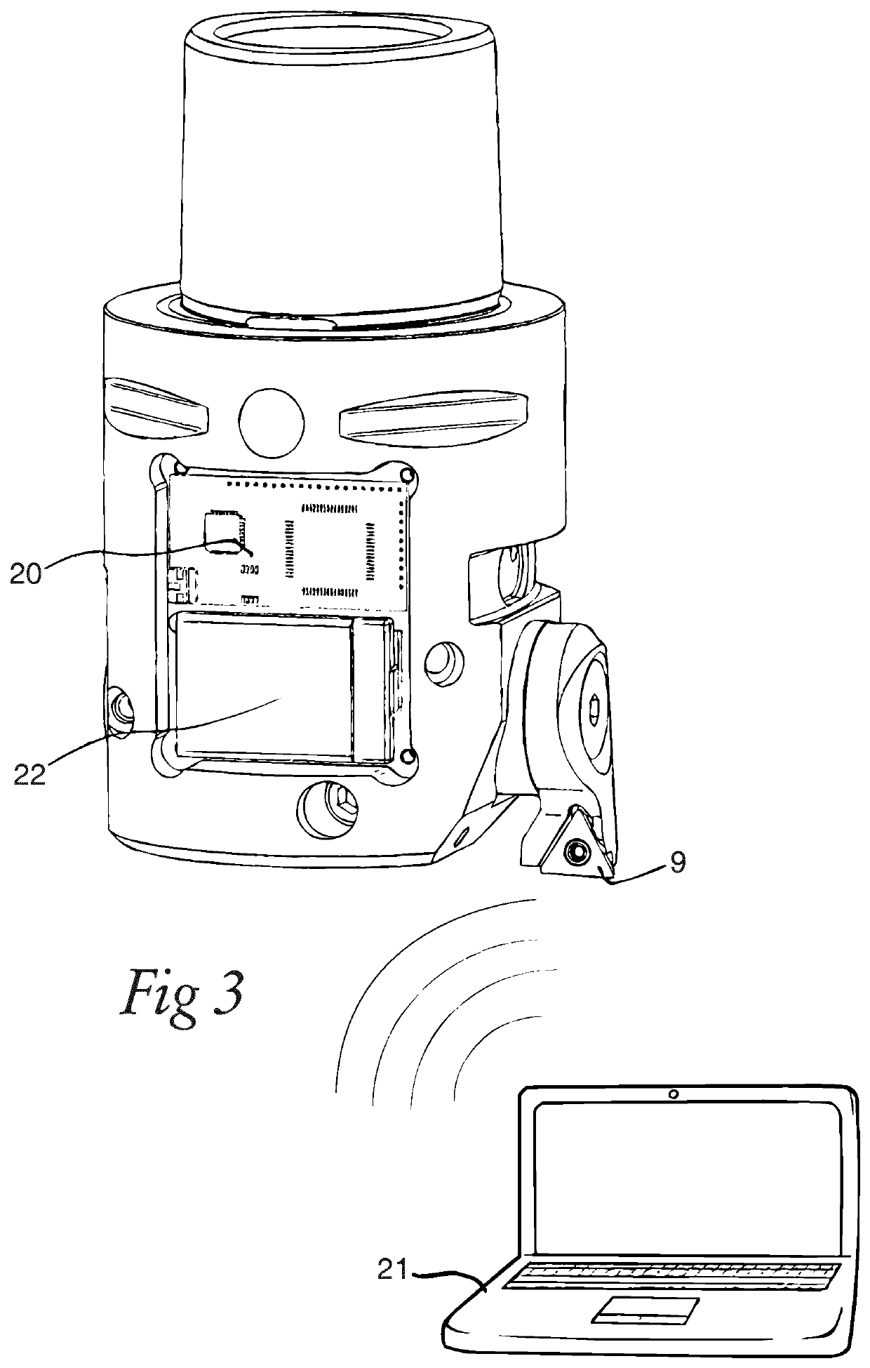
[0034]A boring tool 1 according to a first embodiment of the invention is shown in FIG. 1-3 and reference is made in parallel to these figures when now describing the design of the boring tool. The boring tool has a tool body 2 including a front end 3 and a rear end 4, between which a central rotation axis C extends around which the tool body is rotatable in a direction of rotation R. A slider member 5 is arranged movably inside the tool body along a path P (see dashed line in FIG. 1) extending transversely to the rotation axis C while being directed perpendicularly thereto. An insert pocket 6 (see FIG. 3) is associated with the slider member to move therewith by being arranged on a part 7 secured to the slider member 5 by a screw 8. The insert pocket is configured to receive a cutting insert 9 to be secured therein by a fastening member 10. The cutting insert has a cutting edge 11 and projects from the tool body transversely to the rotation axis C thereof so as to carry out a borin...


PUM


Abstract

A boring tool includes a tool body rotatable around a central rotation axis. A slider member is arranged movably inside the tool body along a path extending transversely to the rotation axis. An insert pocket is associated with the slider member to move therewith and configured to receive a cutting insert with a cutting edge and which projects from the tool body transversely to the rotation axis. A motor member is connected to the slider member and controllable to move the slider member transversely to the rotation axis for changing the distance of the cutting edge to the rotation axis. The motor member is arranged inside the tool body together with the slider member in a cutting part of the tool body at a front end thereof. The motor member is arranged in parallel with the transversal extension of the slider member along said path.

Description

RELATED APPLICATION DATA[0001]This application is a § 371 National Stage Application of PCT International Application No. PCT / EP2017 / 051973 filed Jan. 31, 2017 claiming priority to EP 16162248.5 filed Mar. 24, 2016.TECHNICAL FIELD OF THE INVENTION[0002]The present invention relates to a boring tool comprising[0003]a tool body including a front end and a rear end, between which a central rotation axis extends around which the tool body is rotatable in a direction of rotation,[0004]a slider member which is arranged movably inside the tool body along a path extending transversely to said rotation axis,[0005]an insert pocket associated with the slider member to move therewith and configured to receive a cutting insert to be se-cured therein by a fastening member, which cutting insert has a cutting edge and projects from the tool body transversely to said rotation axis,[0006]a motor member connected to the slider member and controllable to move the slider member transversely to said rota...

Claims


Application Information

Patent Timeline
Patent Type & Authority Patents(United States)
IPC IPC(8): B23B29/034
CPCB23B29/03439B23B2260/062B23B2229/16
Inventor KARLSSON, ROBIN
Owner SANDVIK INTELLECTUAL PROPERTY AB
Why Eureka
Try Eureka