
Self-variable force hydraulic damper

a hydraulic damper and self-variable force technology, applied in the field of shock absorbers, can solve the problem that the hydraulic damper cannot buffer the wind shock, and the above-ground hydraulic damper cannot. achieve the effect of improving the sliding accuracy of the guide seal assembly, moving more smoothly, and increasing the damping for

Active Publication Date: 2021-09-21
NINGBO KASICO SHOCK ABSORBER MFG CO LTD
View PDF8 Cites 1 Cited by
  • Summary
  • Abstract
  • Description
  • Claims
  • Application Information

AI Technical Summary

Benefits of technology

The patent describes a hydraulic damper that can adjust its damping force based on wind pressure on a solar photovoltaic panel. When the wind pressure is high, the hydraulic damper increases its damping force to buffer the wind shocks. When the wind pressure is low, the hydraulic damper adjusts its damping force to ensure a stable and smooth operation of the solar panel. The patent also mentions that the hydraulic damper has improved stability and performance during calm or breeze states, and that it reduces the probability of internal failure during external wind sudden changes.

Problems solved by technology

With regard to the above-mentioned related technologies, the inventor believes that when the solar photovoltaic power generation system faces high winds of a higher scale, the above hydraulic damper cannot buffer the wind shocks generated by high winds of such scale.

Method used


Image

  • Self-variable force hydraulic damper
  • Self-variable force hydraulic damper
  • Self-variable force hydraulic damper

Examples


Embodiment Construction

[0042]The present application will be described in further detail below with reference to FIGS. 1-9.

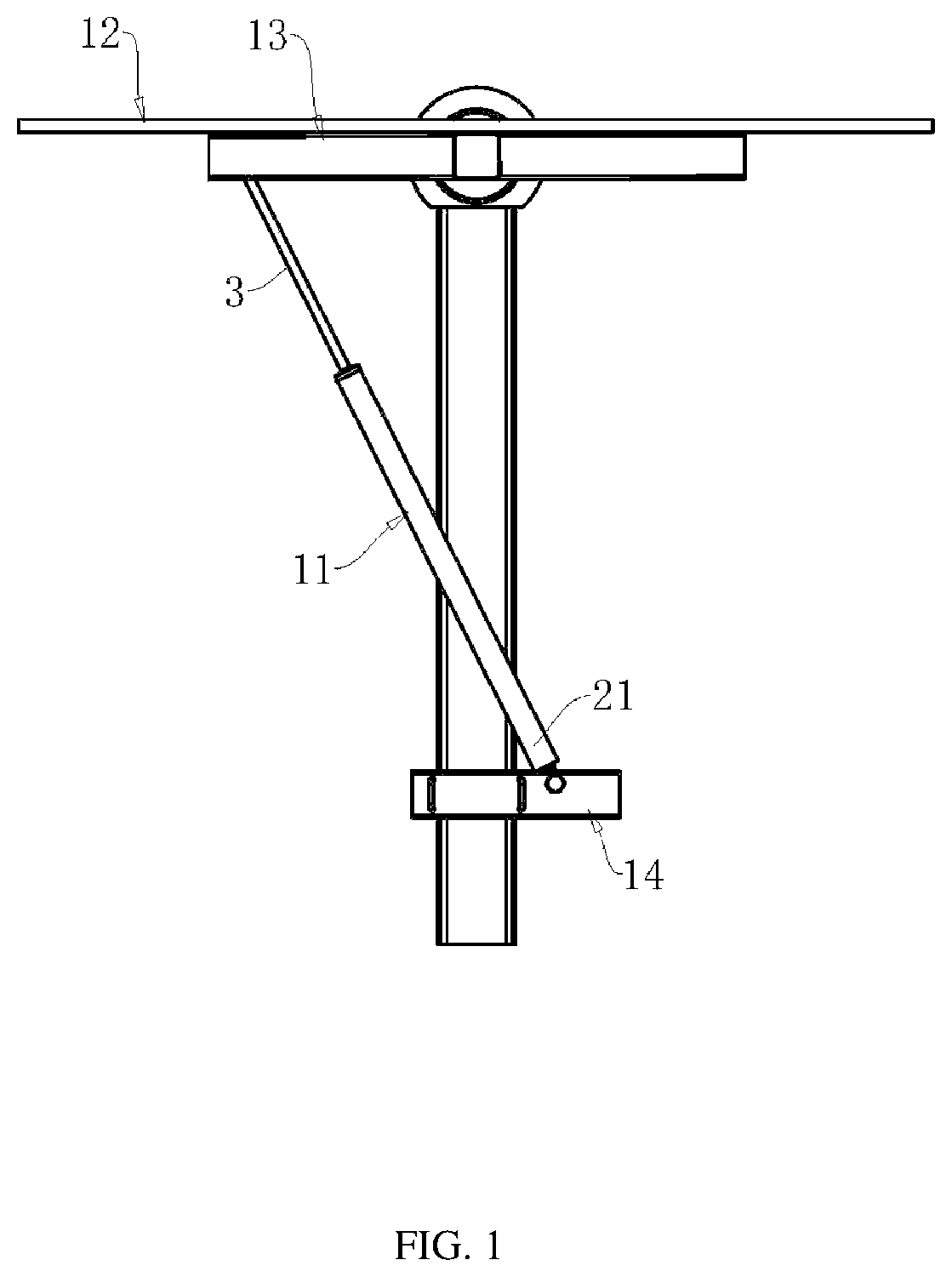
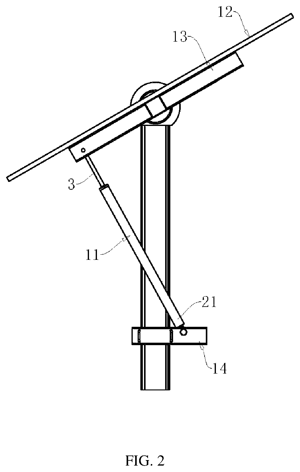
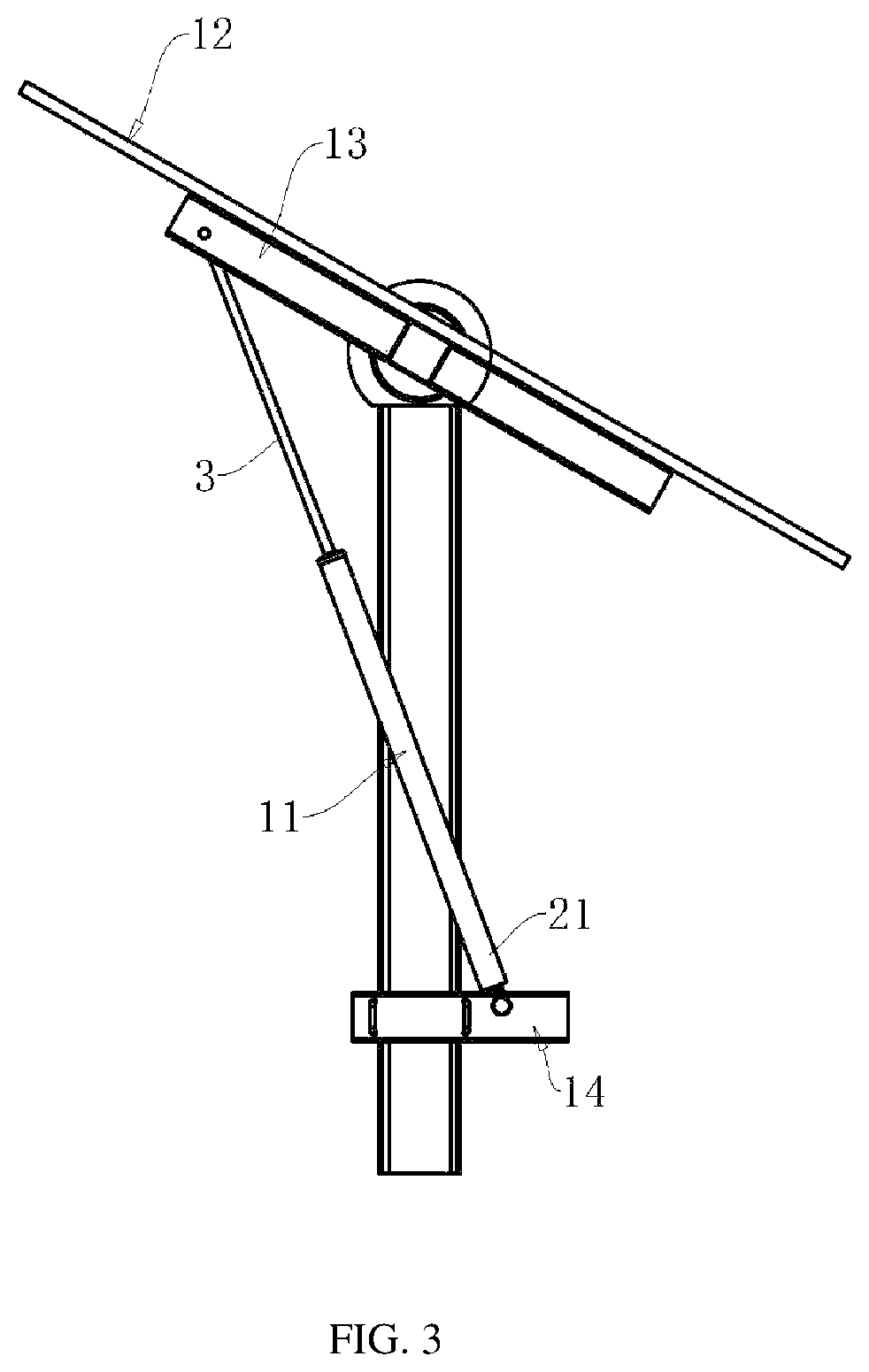
[0043]An embodiment of the present application discloses a self-variable force hydraulic damper 11 applied to a solar photovoltaic power generation system. Referring to FIG. 1, the front end of a piston rod 3 in the self-variable force hydraulic damper 11 is hinged to a solar panel fixed frame 13 where the solar photovoltaic panel 12 is mounted, and an outer cylinder 21 of the self-variable force hydraulic damper 11 is hinged to a base bracket 14. The solar photovoltaic power generation system is also provided with a drive mechanism that drives the solar panel fixed frame 13 to rotate regularly, so that the solar photovoltaic panel 12 can always move towards the direction of the sun to improve the power generation efficiency of the solar photovoltaic panel 12.

[0044]Referring to FIG. 1, it is a schematic diagram of the positional relationship between the solar photovoltaic panel 12 and...


PUM


Abstract

A self-variable force hydraulic damper including a housing assembly, a piston rod and a piston assembly. The piston assembly is mounted on the piston rod and includes a first washer, a first disc spring, a first valve plate, a variable displacement piston, a second valve plate, a second disc spring and a second washer; the piston has a first end face and a second end face, and is further provided with a first flow hole and a second flow hole penetrating the first end face and the second end face respectively; the first valve plate is pressed against the first end face, and the first valve plate closes the first flow hole and does not close the second flow hole; the second valve plate is pressed against the second end face, and the second valve plate closes the second flow hole and does not close the first flow hole.

Description

CROSS-REFERENCE TO RELATED APPLICATION[0001]The present application is a continuation of international application of PCT application No. PCT / CN2021 / 088294 filed on Apr. 20, 2021, which claims the priority benefits of China application No. 202011003752.5 filed on Sep. 22, 2020 and China application No. 202020646451.3 filed on Apr. 26, 2020. The entirety of the above-mentioned patent applications is incorporated herein by reference and made a part of this specification.BACKGROUNDTechnical Field[0002]The present application relates to the field of a shock absorber, and in particular, to a hydraulic damper.Description of Related Art[0003]In the solar photovoltaic power generation system, a solar photovoltaic panel automatically tracks following the solar radiation angle under a program set by a tracker. A hydraulic damper is applied in the solar photovoltaic power generation system to support the solar photovoltaic panel and also buffer wind shocks. The hydraulic damper currently used ...

Claims


Application Information

Patent Timeline
Patent Type & Authority Patents(United States)
IPC IPC(8): F16F9/34F16F9/348F16F9/19H02S20/30
CPCF16F9/3481F16F9/19F16F9/3484H02S20/30F16F2228/066F16F9/3488F16F9/3214F16F9/512F16F9/364F16F9/185H02S20/32F24S50/20Y02E10/47Y02E10/50F24S30/425F16F9/3482F16F9/5126F16F9/585F24S2030/19
Inventor MAO, LINALI, RONG
Owner NINGBO KASICO SHOCK ABSORBER MFG CO LTD
Learn More