Air conditioner and defrost control method therefor

a technology of air conditioner and control method, which is applied in the field of air conditioner, can solve the problems of reducing indoor heating performance and inconvenience for users, and achieve the effects of minimizing the total amount of frost adhered, minimizing the time required, and high reliability

Active Publication Date: 2021-09-28
LG ELECTRONICS INC
View PDF13 Cites 0 Cited by
  • Summary
  • Abstract
  • Description
  • Claims
  • Application Information

AI Technical Summary

Benefits of technology

[0019]According to the embodiment of the present disclosure, when the outdoor heat exchanger is defrosted, it is possible to minimizing the total amount of frost adhered to the entire lowermost heat exchange unit and minimize the time required to complete defrost of the entire outdoor heat exchanger by minimizing the thickness of frost formed on the lowermost heat exchange unit located at the lowermost side.
[0020]In addition, the defrost time of the heat exchange unit located at the lower side of a pair of adjacent heat exchange units may be longer than the defrost time of the heat exchange unit located at the upper side, so that the heat exchange units can be defrosted evenly as a whole.
[0021]In addition, simultaneous defrost to remove frost existing a portion between the pair of adjacent heat exchange units is performed between the defrost of the heat exchange unit located at the upper side and the defrost of the heat exchange unit located at the lower side, thus removing frost existing the portion between the heat exchange units with highly reliability.

Problems solved by technology

The frost adhered to the outdoor heat exchanger disturbs the smooth flow and heat exchange of outdoor air, thus causing a decrease in indoor heating performance.
However, the air conditioner as described above has disadvantages that it is impossible to heat a room while the defrost operation is be performed (that is, during the defrost operation) and may provide inconvenience to a user.

Method used


Image

  • Air conditioner and defrost control method therefor
  • Air conditioner and defrost control method therefor
  • Air conditioner and defrost control method therefor

Examples


Embodiment Construction

[0031]Hereinafter, specific embodiments of the present disclosure will be described in detail with reference to the drawings.

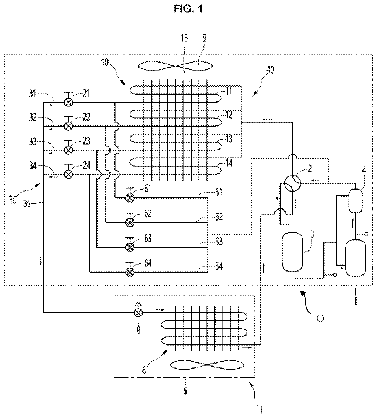
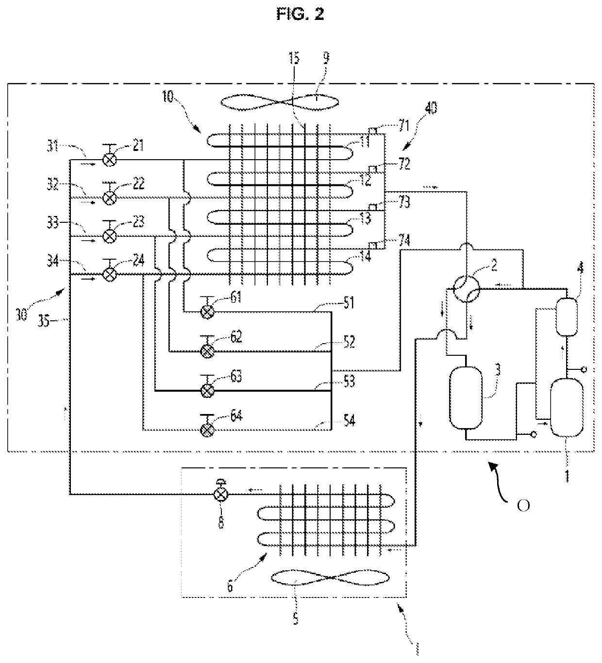
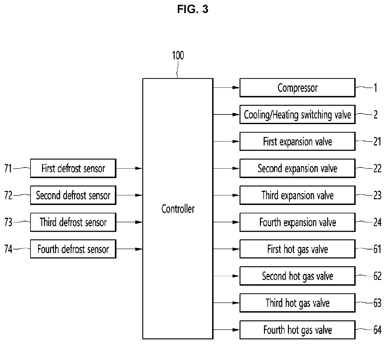
[0032]FIG. 1 is a diagram showing a flow of refrigerant in a cooling operation of an air conditioner according to an embodiment of the present disclosure, FIG. 2 is a diagram showing a flow of refrigerant in a general heating operation of an air conditioner according to an embodiment of the present disclosure, and FIG. 3 is a control block diagram of an air conditioner according to an embodiment of the present disclosure.

[0033]An air conditioner may include a compressor 1, a cooling / heating switching valve 2, an indoor fan 5, an indoor heat exchanger (or indoor unit) 6, an outdoor fan 9, and an outdoor heat exchanger (or outdoor unit) 10.

[0034]The compressor 1 may be composed of an inverter compressor, and an input frequency thereof may be changed according to a load of the indoor heat exchanger 6.

[0035]A compressor suction flow path and a compressor discharge...


PUM


Abstract

An air conditioner includes an outdoor heat exchanger in which N heat exchange units are spaced apart from one another sequentially in a vertical direction N expansion valves respectively connected to the N heat exchange units; N hot gas pipes respectively connected to the N heat exchange units; N hot gas valves respectively installed in the N hot gas pipes; and a controller configured to control the N expansion valves and the N hot gas valves to defrost the N heat exchange units, wherein the controller is configured to defrost a bottom heat exchange unit first, then defrost a top heat exchange unit, and defrost the heat exchange units located under the top heat exchange unit sequentially from a second highest heat exchange unit to the bottom heat exchange unit after defrosting the top heat exchange unit.

Description

CROSS-REFERENCE TO RELATED PATENT APPLICATIONS[0001]This application is a U.S. National Stage Application under 35 U.S.C. § 371 of PCT Application No. PCT / KR2019 / 012425, filed Sep. 24, 2019, which claims priority to Korean Patent Application No. 10-2018-0150743, filed Nov. 29, 2018, whose entire disclosures are hereby incorporated by reference.TECHNICAL FIELD[0002]The present disclosure relates to an air conditioner, and more particularly, to an air conditioner capable of continuously performing heating operation while dividing and defrosting an outdoor heat exchanger in the case of heating operation.BACKGROUND ART[0003]In general, an air conditioner is an apparatus for cooling or heating a room using a cooling cycle including a compressor, an outdoor heat exchanger, an expansion mechanism, and an indoor heat exchanger.[0004]The air conditioner may be composed of a cooler that cools the room, or may be composed of an air conditioner (that is, a heat pump) for air cooling and heating...

Claims


Application Information

Patent Timeline
Patent Type & Authority Patents(United States)
IPC IPC(8): F25B47/02F24F11/42F25B6/02
CPCF24F11/42F25B6/02F25B47/02F25B2600/21F25B2700/21175F25B2600/2513F25B2700/197F25B13/00F25B41/30F25B49/02F25B5/02F25B47/022F25B2600/2507F25B2600/2519F25B2313/0253F25B2347/021F25B2313/0251F25B2313/0315F25B2700/21162F25B2600/01
Inventor LEE, JAEWONCHOI, WOOJOOPARK, JINHYOUNGSHIN, YOUNGJOO
Owner LG ELECTRONICS INC
Why Eureka
Try Eureka