
Methods of intracerebral implant delivery

a technology of intracerebral implants and stents, which is applied in the field of medical devices and methods, can solve the problems of high risk of stroke and thromboembolic complications, aneurysms in brain vessels by endovascular stents and stent-like devices, and the difficulty of treating arteriosclerosis, etc., and achieves the effect of fast, easy and efficient endovascular implantation

Active Publication Date: 2021-10-19
ROUTE 92 MEDICAL INC
View PDF139 Cites 0 Cited by
  • Summary
  • Abstract
  • Description
  • Claims
  • Application Information

AI Technical Summary

Benefits of technology

The patent describes an anchoring delivery system for use in cerebrovascular diseases that can provide support during the delivery of implants such as stents and flow diverters. This system can be used when there are obstacles or difficult anatomy in the way of the procedure. It can help to make the procedure faster, easier, and more efficient. The system includes an anchor and a guide-sheath that can be attached to a tether, which is then used to deliver the implant to the treatment site. The guide-sheath can be attached to the tether at a point near the entrance of the target vessel or at a point more distal to the entrance. The system can prevent prolapse of the guide-sheath and resist tension during the procedure. Overall, this system can provide better support and facilitate the delivery of implants in cerebrovascular diseases.

Problems solved by technology

Other serious vascular defects include aneurysm in which a bulge or bubble protrudes out in a radial direction from the vessel that, if left untreated, may continue expanding until it bursts thereby causing hemorrhaging from the vessel.
Treating arteriosclerosis and aneurysms in vessels of the brain by endovascular implantation of stents and stent-like devices is particularly challenging due, in part, to the tortuosity of the vasculature and the small size of the vessels.
Further, the risk of stroke and thromboembolic complications is high due to the release of thrombotic material during delivery of the stent and, in the case of flow diverters for treatment of aneurysm, can block blood flow to branch vessels.
Stent length also poses a risk for further thromboembolic complications.

Method used


Image

  • Methods of intracerebral implant delivery
  • Methods of intracerebral implant delivery
  • Methods of intracerebral implant delivery

Examples


Embodiment Construction

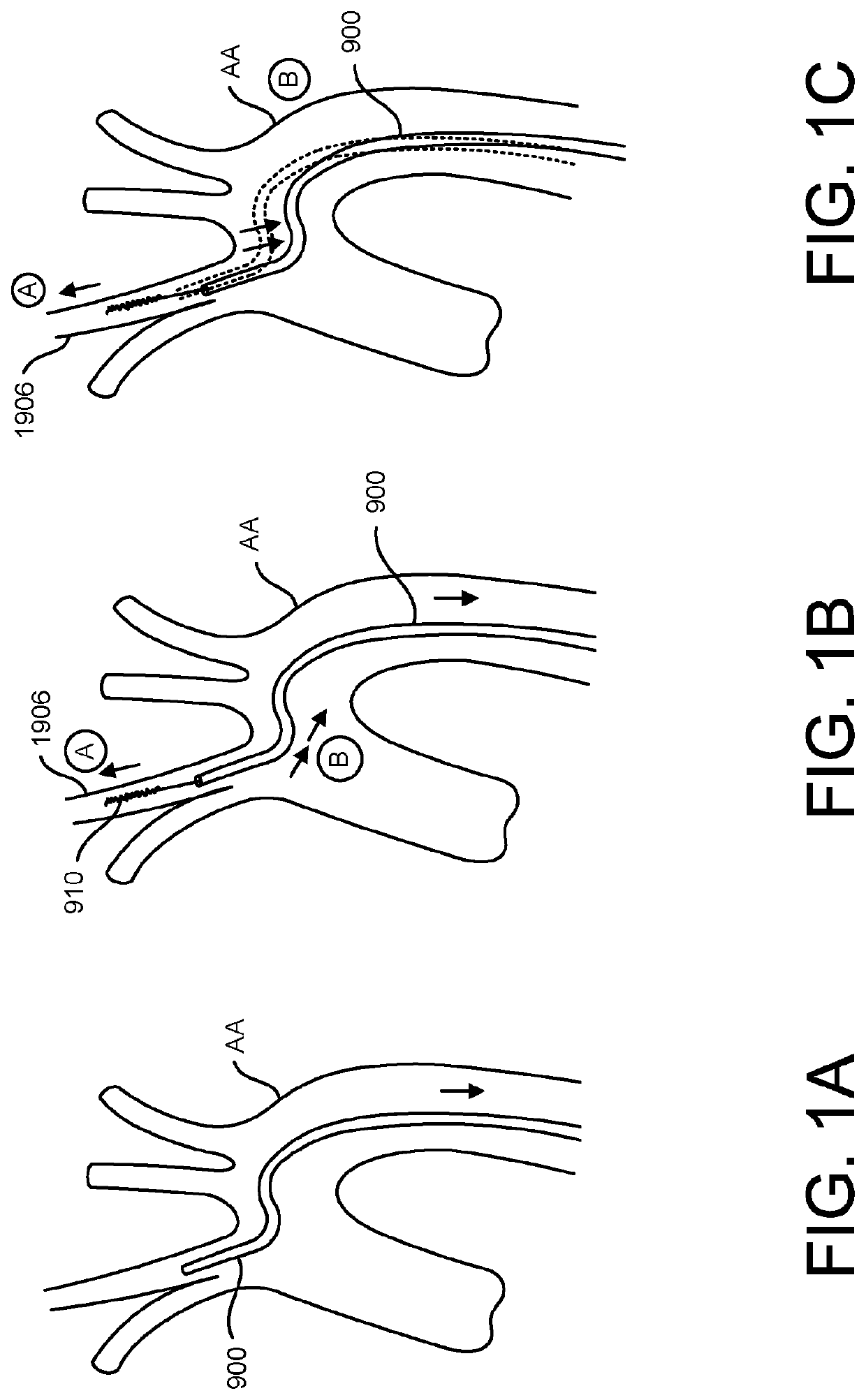
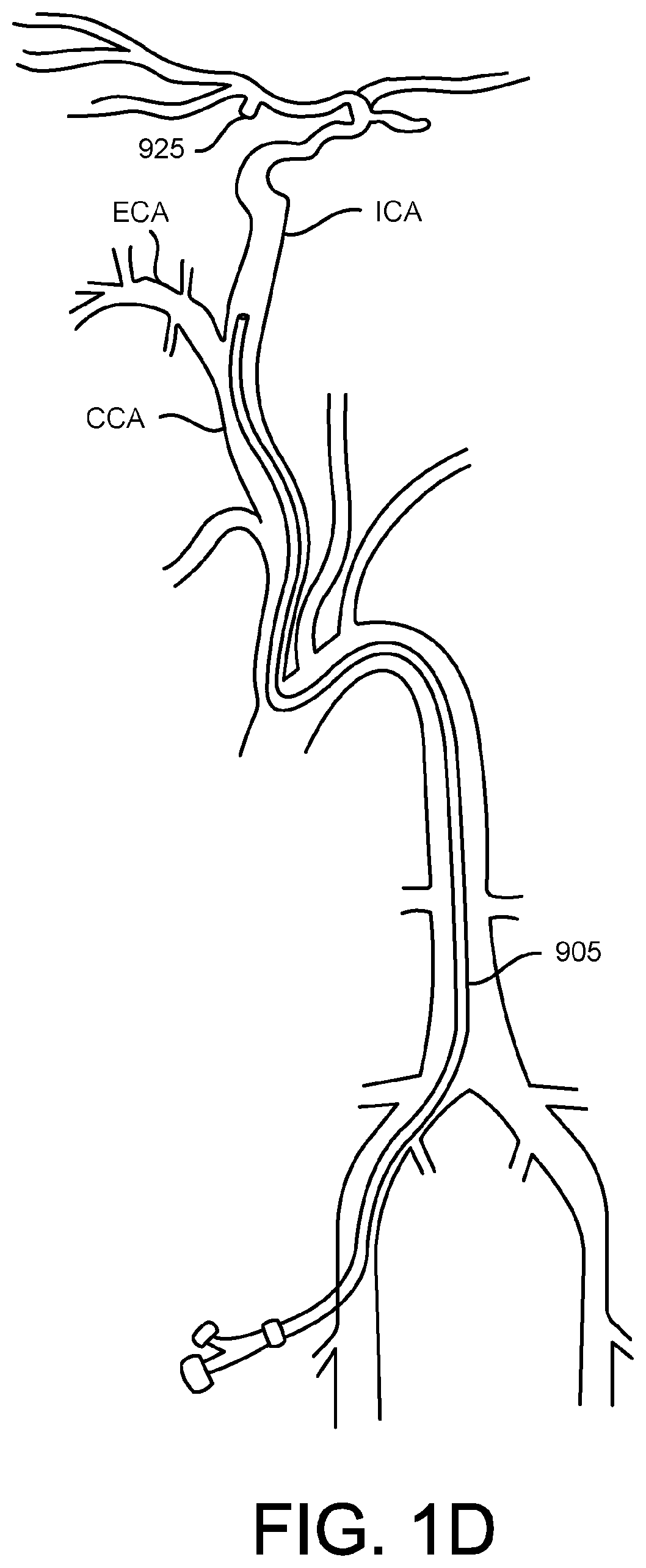
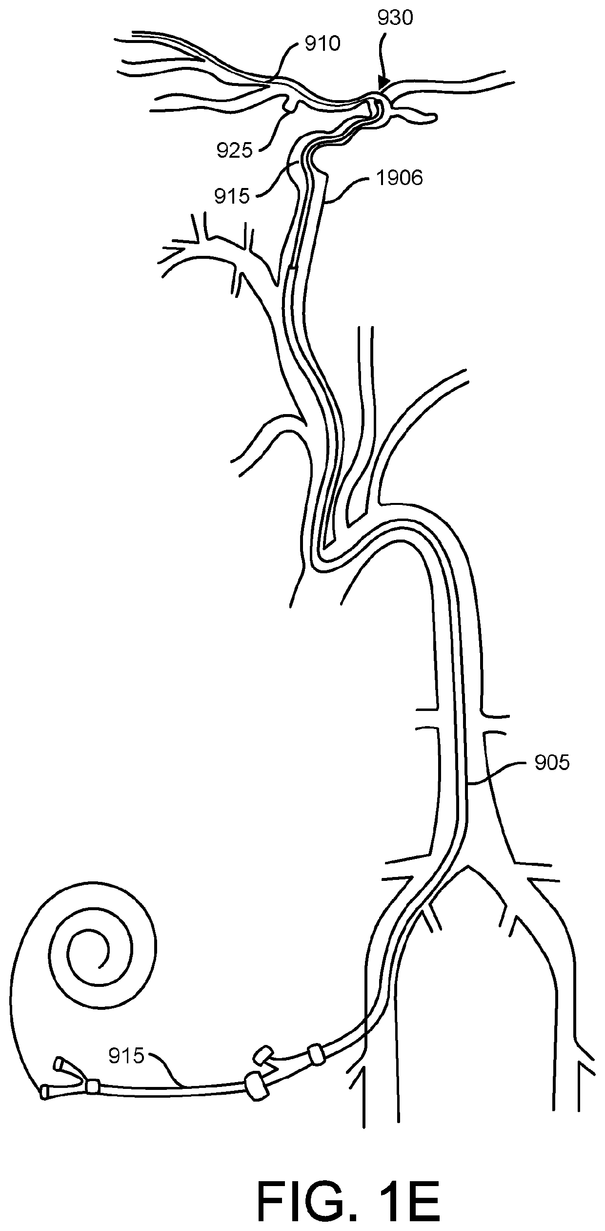
[0081]Endovascular access of the neurovasculature requires navigation of vessels, often tortuous and diseased, which can complicate delivery of devices such as intracerebral stents and their delivery systems. Resistance points during advancement of various implantable devices through the vessel can lead to a chain reaction of events involving the buckling and storage of tension within the catheter length. Further, many cases involve a trial and error iterative process of different constructs of supporting catheters and stiff wires to build a “tower” into the intracerebral vasculature—each iteration involving further guidance and support. This can be traumatic to the vessel through which the devices are passed and ultimately, the entire system can lose column strength and such that the devices fail to traverse to the desired location.

[0082]To access the cerebral anatomy, guide catheters and guide sheaths are used to direct interventional devices, such as stents, coils, and flow diver...


PUM


Abstract

The method of delivering an implant in an intracranial vessel includes deploying an anchor of a tethering device in an anchoring vessel forming a first fixation point and advancing a guide-sheath to a location near the anchoring vessel. The tethering device has a tether extending proximally from the anchor and the guide-sheath has at least one lumen. The method includes attaching the guide-sheath to the tether of the tethering device forming a second fixation point proximal to the first fixation point, delivering an implant through the lumen of the guide-sheath towards a treatment site distal to the first fixation point and located within an intracranial vessel, and deploying the implant at the treatment site. Related devices, systems, and methods are also provided.

Description

CROSS-REFERENCE TO RELATED APPLICATIONS[0001]This application is a National Stage entry, filed under 35 U.S.C. § 371, of International Application No. PCT / US2016 / 043742, filed on Jul. 22, 2016, and claims priority to U.S. Provisional Application Nos. 62 / 196,613, filed Jul. 24, 2015, entitled “Anchoring Guide System;” and 62 / 275,963, filed Jan. 7, 2016, entitled “Method of Intracerebral Implant Delivery;” and 62 / 275,939, filed Jan. 7, 2016, entitled “Anchoring Delivery system;” and 62 / 301,857, filed Mar. 1, 2016, entitled “Anchoring Delivery System.” Priority to the aforementioned filing date is claimed and the entire contents of each are hereby incorporated by reference herein in their entireties and for all purposes.FIELD[0002]The present technology relates generally to medical devices and methods, and more particularly, to delivery systems and methods for delivering implant devices to a target anatomy.BACKGROUND INFORMATION[0003]Vascular disease caused by stenosis or narrowing of ...

Claims


Application Information

Patent Timeline
Patent Type & Authority Patents(United States)
IPC IPC(8): A61F2/966A61F2/95A61B17/12A61F2/07A61F2/915A61F2/06
CPCA61F2/966A61B17/1214A61B17/12109A61B17/12118A61F2/95A61B17/12113A61B2017/1205A61F2/07A61F2/915A61F2002/068A61F2002/91558A61F2002/91566A61F2002/91575A61F2220/0016A61F2230/0091A61F2/82A61B17/12036
Inventor CHOU, TONY M.ENGLISH, JOEY
Owner ROUTE 92 MEDICAL INC
Learn More