Flow sensor devices and systems

a flow sensor and flow rate technology, applied in the direction of liquid/fluent solid measurement, volume metering, instruments, etc., can solve the problems of affecting the accuracy of clamp-on ultrasonic flow meters, difficult to obtain additional installation details, and difficult to detect inner wall smoothness and eccentricity of pipes, so as to simplify manufacturing and minimize inventory

Active Publication Date: 2021-10-19
BLUE WHITE INDS
View PDF124 Cites 11 Cited by
  • Summary
  • Abstract
  • Description
  • Claims
  • Application Information

AI Technical Summary

Benefits of technology

[0004]Traditionally, clamp-on transducers have been favored by ultrasonic flow meter manufacturers due to their one-size-fits-all transducer design that simplifies manufacturing and minimizes inventory. Clamp-on transducer type flow meters may be preferred because they have no moving parts, no wetted materials, and do not require a system shut-down for installation.
[0022]In some embodiments, the assembly includes an inner cup portion positioned at least partially within the elongate portion of the outer cup portion, wherein the transducer is positioned within the inner cup portion and wherein a connection between the inner cup portion and the outer cup portion forms a seal to inhibit or prevent fluid ingress into the elongate portion of the outer cup portion.

Problems solved by technology

Furthermore, additional installation details are often difficult to obtain and detect, such as: the smoothness of the outer pipe wall, the smoothness of the inner pipe wall (defects in surface), and the eccentricity of the pipe (which may not be zero).
The inner wall smoothness and eccentricity of the pipe are difficult to determine in the field and can drastically affect the accuracy of clamp-on ultrasonic flow meters.
This grease needs to be replaced periodically, especially in outdoor or dry locations, leading to increased maintenance requirements.
Due to the number of installation details needed for a successful installation of clamp-on ultrasonic transducers, successful installation may not occur in every situation.
Additionally, clamp-on transducers are susceptible to being unintentionally moved by external forces, such as a passers-by knocking or hitting transducers by mistake.
Any shift in the clamp-on transducer can jeopardize the flow measurement accuracy.

Method used


Image

  • Flow sensor devices and systems
  • Flow sensor devices and systems
  • Flow sensor devices and systems

Examples


Embodiment Construction

[0051]While the present description sets forth specific details of various embodiments, it will be appreciated that the description is illustrative only and should not be construed in any way as limiting. Furthermore, various applications of such embodiments and modifications thereto, which may occur to those who are skilled in the art, are also encompassed by the general concepts described herein.

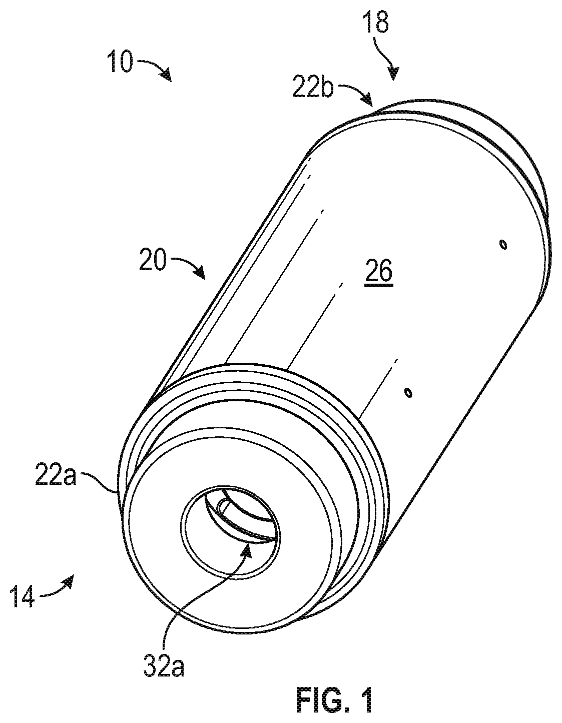
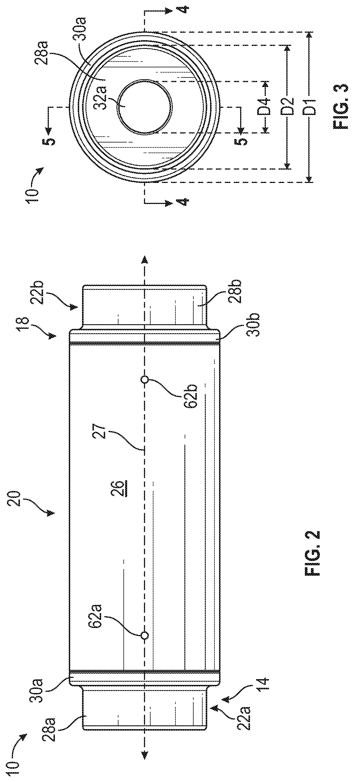
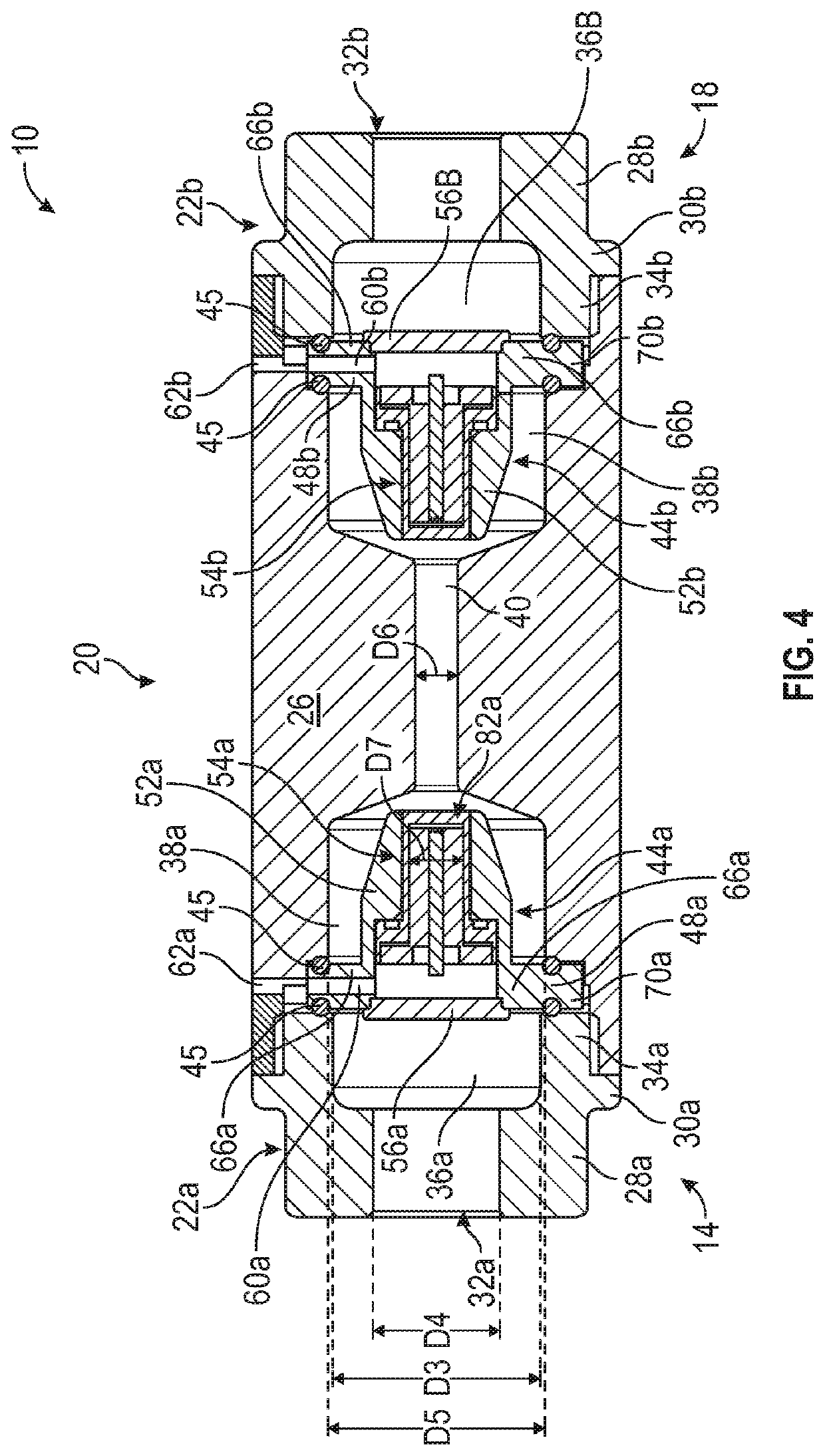
[0052]Ultrasonic transducer assemblies are used to measure flow characteristics of fluid flowing through pipes or other fluid lines. The transducer assemblies can include two or more transducers configured to send and receive ultrasonic signals through the fluid line and corresponding fluid. Transducer assemblies can indicate such parameters as the velocity of the fluid through the fluid line. Transducer assemblies can be used in conjunction with pumps and other devices to monitor and / or control flow rates through fluid lines.

[0053]The transducers used in traditional transducer assemblies ...


PUM


Abstract

A flow rate assembly can include a housing having a measurement channel extending along the housing axis and through a portion of the housing between the first and second ends of the housing, an outer cup portion positioned at least partly within the housing, and a transducer positioned within the outer cup portion and sealed from fluid flow past the outer cup portion, the transducer having a width perpendicular to the housing axis and greater than the width of the measurement channel, the transducer configured to generate an ultrasonic signal and to direct the ultrasonic signal through the measurement channel.

Description

CROSS REFERENCE TO RELATED APPLICATIONS[0001]This application claims the benefit under 35 U.S.C. 119(e) to U.S. Provisional App. No. 62 / 399,216, filed Sep. 23, 2016, titled FLOW SENSOR DEVICES AND SYSTEMS. The entire content of the above-identified patent application is incorporated by reference herein and made a part of this specification. Any and all applications for which a foreign or domestic priority claim is identified in the Application Data Sheet as filed with the present application are hereby incorporated by reference under 37 CFR 1.57.TECHNICAL FIELD[0002]Certain embodiments discussed herein relate to devices and systems for measuring flow rate of fluid through pipes.DISCUSSION OF THE RELATED ART[0003]Many varieties of ultrasonic transducer assemblies exist, employing a variety of techniques and mechanisms for installing the transducer assemblies on a fluid conduit. However, such devices and certain components thereof have various limitations and disadvantages.SUMMARY OF ...

Claims


Application Information

Patent Timeline
Patent Type & Authority Patents(United States)
IPC IPC(8): G01F1/66G01F15/18G01F15/14
CPCG01F1/66G01F1/662G01F1/667G01F15/14G01F15/18G01N29/22
Inventor GLEDHILL, III, ROBERTNGUYEN, JOHNMURPHY, PATRICK M.MCDOWELL, WILLIAM M.
Owner BLUE WHITE INDS
Why Eureka
Try Eureka