Device and method for bonding alignment

a technology of bonding alignment and devices, applied in semiconductor devices, semiconductor/solid-state device details, chemistry apparatus and processes, etc., can solve the problems of affecting the final alignment accuracy, high the inability to control the errors that may arise from the movement of the substrate during the alignment process, so as to reduce the complexity of the associated apparatus, control the global alignment accuracy, and reduce the complexity of the apparatus

Active Publication Date: 2021-10-19
SHANGHAI MICRO ELECTRONICS EQUIP (GRP) CO LTD
View PDF18 Cites 0 Cited by
  • Summary
  • Abstract
  • Description
  • Claims
  • Application Information

AI Technical Summary

Benefits of technology

[0028]Compared to the prior art, the present invention offers the following benefits: in the apparatus and method of the invention, the press assembly comprises a first chuck and a rotatable second chuck; when the support surfaces of the first chuck and the rotatable second chuck are not parallel to each other, the second chuck is rotated to make them parallel. The first substrate is then loaded on the first chuck, and the alignment marks on the first substrate are observed using the objective lens group disposed on one side of the press assembly. The second substrate is then loaded on the second chuck, and the alignment marks on the second chuck are also observed with the objective lens group. Based on the observations performed by the objective lens group, the two substrates are moved so that the alignment marks thereon are aligned and hence the two substrates themselves are aligned. According to the present invention, the chucks are adjusted, prior to the alignment of the substrates. This dispenses with the need for employment of high-precision components and reduces the complexity of the apparatus. In particular, a global alignment accuracy between the substrates can be ascertained. Moreover, adjusting the chucks first can ensure control of the global alignment accuracy between the substrates, and in particular, can reduce wedge-shaped errors between the substrates that may result from deformations of the substrates during bonding.

Problems solved by technology

In recent years, as the requirements on substrate alignment are getting more and more demanding, and since substrates with larger diameters are being increasingly used, traditionally ignorable errors, such as the errors arising from mechanical movement and substrate deformation, have increased their influence on alignment accuracy currently on the order of microns or less to an extent that they may affect the final alignment accuracy.
This imposes strict requirements on the calibration of the objective lens pairs and makes it impossible to control errors that may arise from movement of the substrates during the alignment process.
Despite its ability to align the alignment marks with very high accuracy, this method requires additional use of a large number of high-precision sensors, which lead to a high complexity of the associated apparatus.
Moreover, it is still incapable of detecting global errors caused by substrate deformation or other reasons, in particular the errors in substrate portions other than the alignment marks.

Method used


Image

  • Device and method for bonding alignment
  • Device and method for bonding alignment
  • Device and method for bonding alignment

Examples


embodiment 1

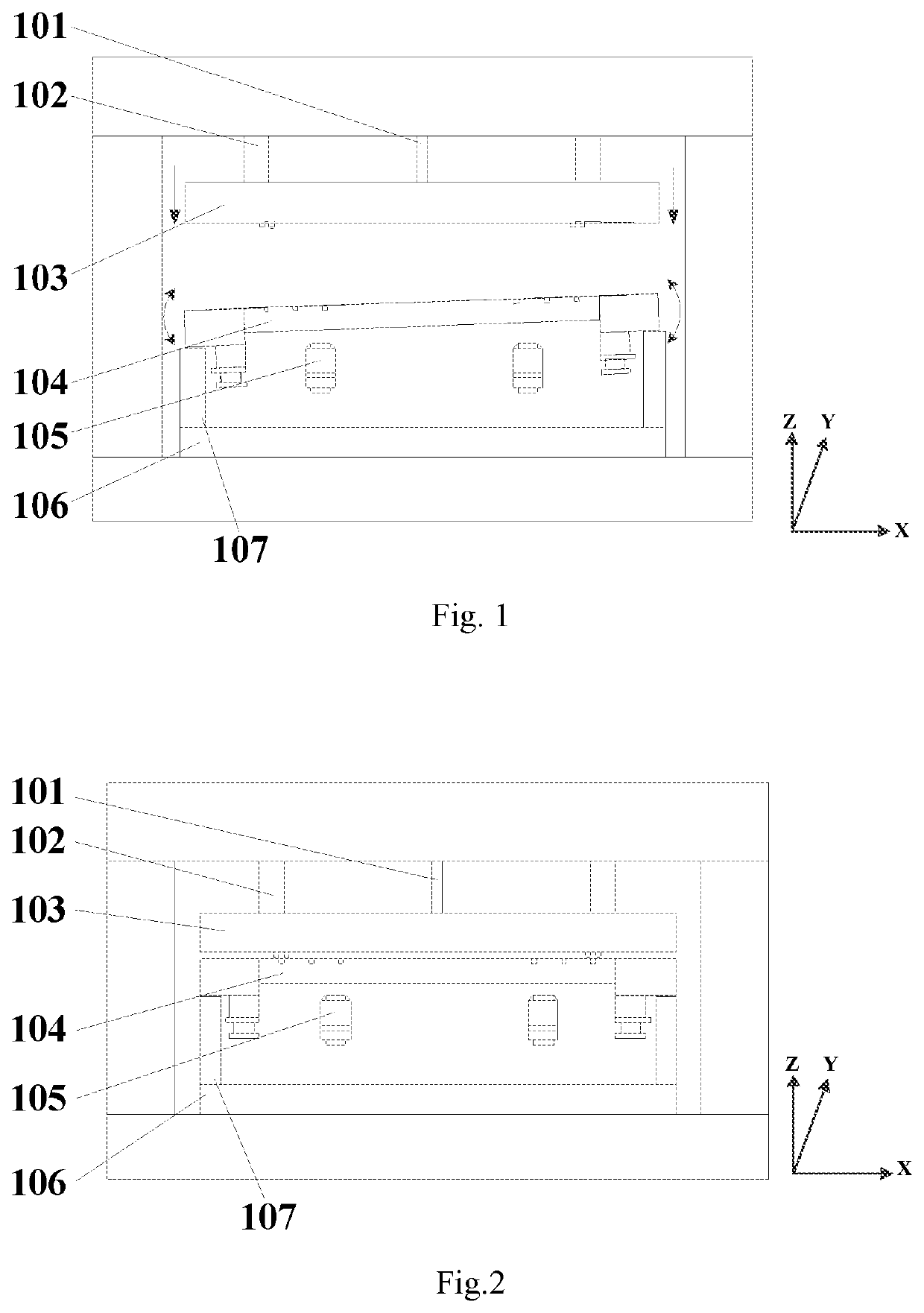
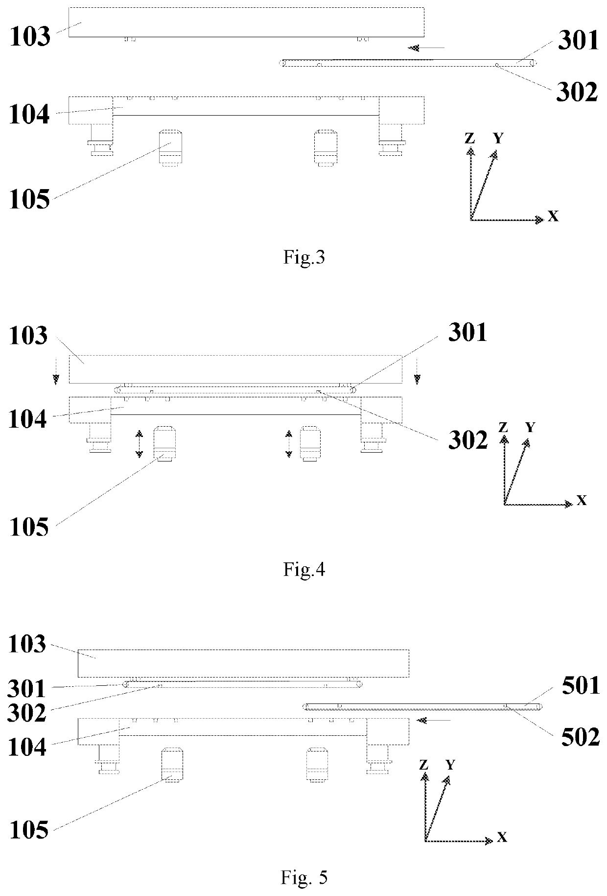
[0046]Referring to FIG. 1, the present invention provides an apparatus for bonding alignment of two substrates. The apparatus for bonding alignment includes a press assembly comprising, from top to bottom, an upper actuator 102, an upper chuck 103 in fixed connection to the upper actuator 102, a lower chuck 104 having a support surface facing toward a support surface of the upper chuck 103, a leveling device 107 in fixed connection to the lower chuck 104 and a lower actuator 106 in fixed connection to the leveling device 107. The upper chuck 103 is electrically connected to a pressure sensor 101 for detecting a pressure applied by the upper chuck 103 to the lower chuck 104. The upper actuator 102 can drive the upper chuck 103 to move vertically.

[0047]Herein, an X-Y-Z three-dimensional coordinate system is defined by an X-axis extending horizontally, a Z-axis extending vertically and a Y-axis extending perpendicular to the X-Z plane defined by the X and Z axes.

[0048]Referring to FIG....

embodiment 2

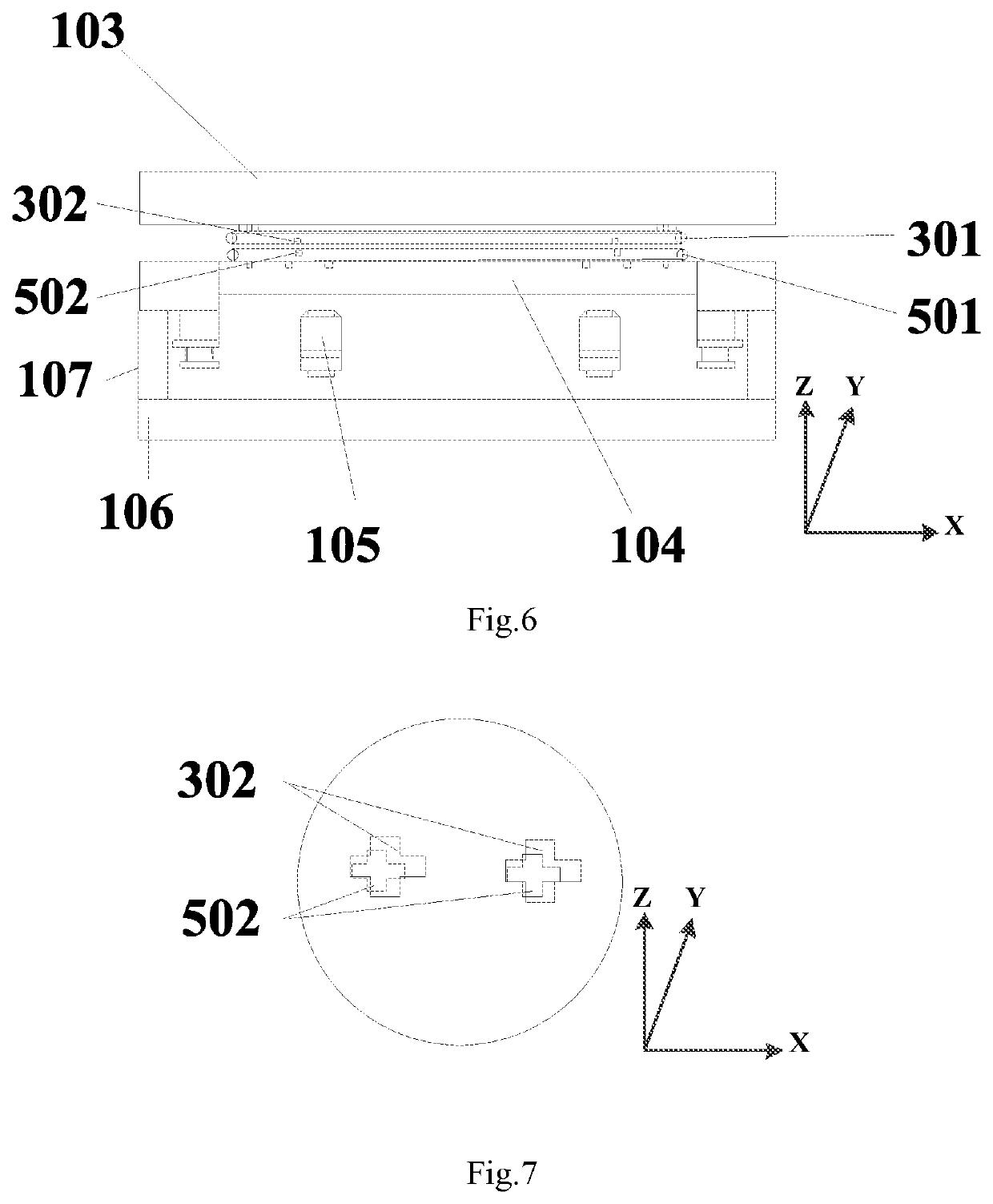
[0062]This embodiment differs from Embodiment 1 in that the objective lens group 105 is disposed on one side of the upper chuck 103. Referring to FIG. 10, the upper chuck 103 is fixed to the upper actuator 102 and is made of a transparent material allowing the passage of light sources. Similarly, the leveling device 107 is fixedly connected to the lower actuator 106, and the lower chuck 104 is fixed to the leveling device 107. The lower chuck 104 is able to yaw in two degrees of freedom (i.e., Rx and Ry).

[0063]Referring to FIG. 11, the upper chuck 103 moves downward with a constant orientation under the action of the upper actuator 102. Upon the pressure sensor 101 having sensed that a pressure exerted by the upper chuck 103 on the lower chuck 104 reaches a predetermined value, it is determined that a wedge-shaped error has been eliminated, and the upper actuator 102 is then deactivated. The lower chuck 104 maintains this orientation with the aid of the leveling device 107.

[0064]Ref...


PUM

PropertyMeasurementUnit
pressureaaaaaaaaaa
altitudeaaaaaaaaaa
heightaaaaaaaaaa

Abstract

An apparatus and method for bonding alignment are provided. The apparatus for bonding alignment includes a press assembly and an objective lens group (105) disposed on one side of the press assembly. The press assembly includes a first chuck (103) and a rotatable second chuck (104). When support surfaces of the first and second chucks are not parallel to each other, the second chuck is rotated to make the two support surfaces parallel. A first substrate (301) is then loaded on the first chuck, and alignment marks (302) on the first substrate are observed using the objective lens group disposed on one side of the press assembly. A second substrate (501) is loaded on the second chuck, and alignment marks (502) on the second substrate are also observed with the objective lens group. Based on an observation result by the objective lens group, the two substrates are moved so that the alignment marks thereon are aligned and hence the two substrates themselves are aligned. In this method, the chucks are adjusted, prior to the alignment of the substrates. This dispenses with the need for employment of high-precision components and reduces the complexity of the apparatus. Moreover, adjusting the chucks first can ensure control of a global alignment accuracy between the substrates, and in particular, can reduce wedge-shaped errors between the substrates that may result from deformations of the substrates during bonding.

Description

TECHNICAL FIELD[0001]The present invention relates to the field of semiconductor technology and, in particular, to an apparatus and method for bonding alignment.BACKGROUND[0002]In semiconductor processes, two semiconductor devices are generally required to be bonded together. Typically, two wafers, one wafer and one glass plate or two glass plates are bonded together. For convenience of description, the wafers and glass plates are collectively referred to as substrates hereinafter. In a current semiconductor process, before two substrates are bonded together, the two substrates are required to be aligned with each other by a bonding apparatus.[0003]In recent years, as the requirements on substrate alignment are getting more and more demanding, and since substrates with larger diameters are being increasingly used, traditionally ignorable errors, such as the errors arising from mechanical movement and substrate deformation, have increased their influence on alignment accuracy current...

Claims


Application Information

Patent Timeline
Patent Type & Authority Patents(United States)
IPC IPC(8): B32B41/00H01L21/67H01L21/68H01L21/687H01L23/544
CPCH01L21/67092H01L21/681H01L21/68764H01L23/544H01L2223/54426H01L24/75H01L2224/753H01L2224/75744H01L2224/75745H01L2224/75753H01L2224/75802H01L2224/75822H01L2224/7592H01L21/185H01L21/682
Inventor ZHU, ZHIZHAO, JIANJUNHUO, ZHIJUN
Owner SHANGHAI MICRO ELECTRONICS EQUIP (GRP) CO LTD
Why Eureka
Try Eureka