
Method for feeding in an electrical alternating current

a technology of electrical alternating current and feeding method, which is applied in the direction of electric generator control, machines/engines, mechanical equipment, etc., can solve the problems of restricted operating range and harmonics that do not m

Active Publication Date: 2021-10-26
WOBBEN PROPERTIES GMBH
View PDF20 Cites 0 Cited by
  • Summary
  • Abstract
  • Description
  • Claims
  • Application Information

AI Technical Summary

Benefits of technology

The patent proposes a method for controlling an active filter in an inverter system that reduces harmonics in the current provided to an electrical grid. The active filter is controlled directly based on the activation signals from the inverter switches. This results in almost the same signal transit times between the controller and the switches, which allows for filtering the inverter current without measuring it. The method also eliminates the need for initializing and reconfiguring the active filter, minimizing harmonics and providing a more efficient and effective way to filter harmonics.

Problems solved by technology

However, electrical inverters also have a series of disadvantages, for example, the electrical alternating current provided by an electrical inverter has a high harmonic content, i.e., the electrical alternating current or the electrical inverter current has a large number of harmonics of different orders, which are undesirable from the viewpoint of the electrical supply grid.
A disadvantage of the previously known filters is, in particular, the restricted operating range in the case of passive filters or the high signal transit times in the case of active filters, which have the effect that, in spite of these precautions, the electrical alternating current generated by the generator, rectified by the inverter and filtered by the filter has harmonics that do not meet the requirements of the electrical supply grid, in particular in countries with high requirements which in particular have a weak electrical supply grid, such as, for example, Brazil.

Method used


Image

  • Method for feeding in an electrical alternating current
  • Method for feeding in an electrical alternating current
  • Method for feeding in an electrical alternating current

Examples


Embodiment Construction

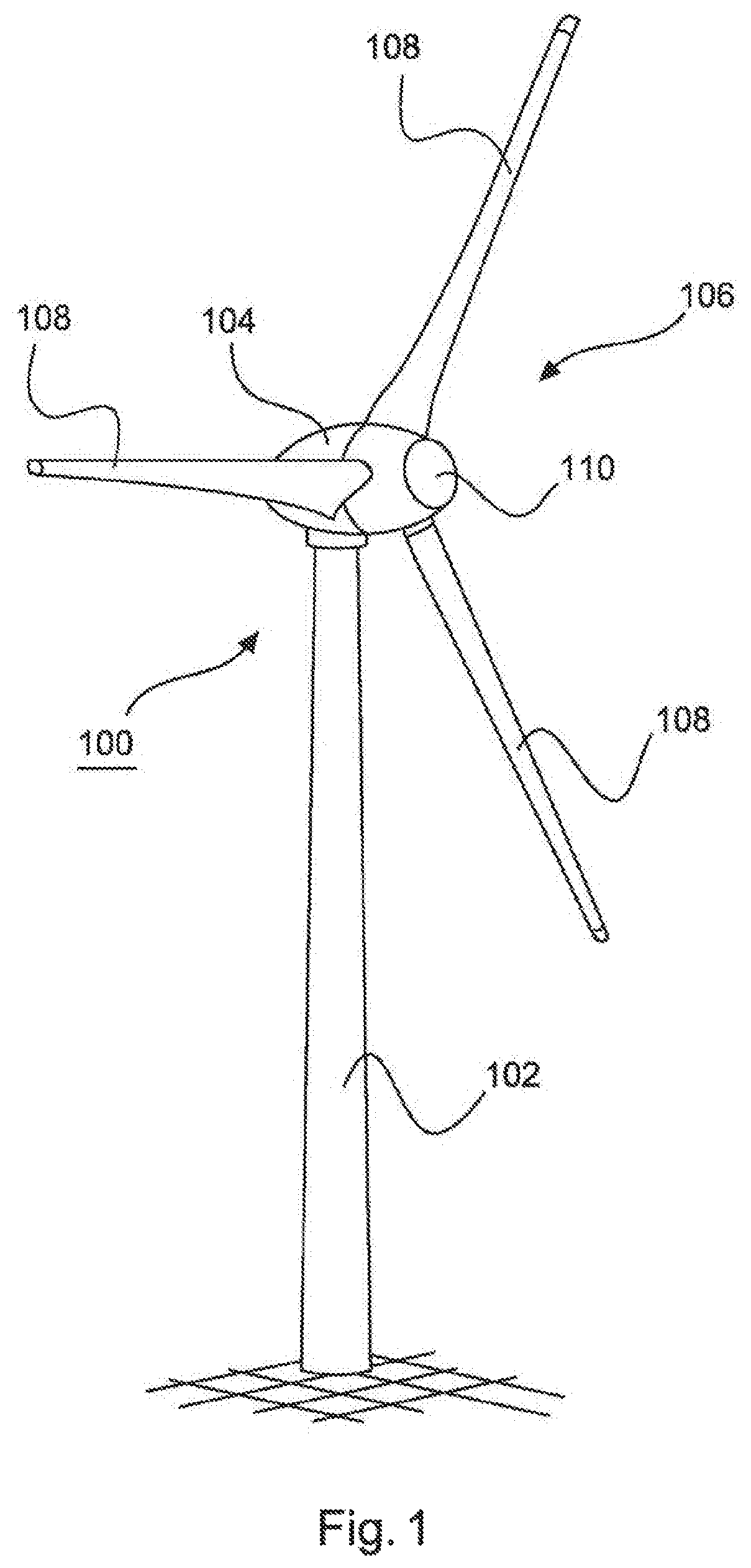
[0082]FIG. 1 shows a wind power installation 100 for feeding electrical alternating current into an electrical supply grid.

[0083]For this purpose, the wind power installation 100 has a tower 102 and a nacelle 104. An aerodynamic rotor 106 with three rotor blades 108 and a spinner 110 is arranged on the nacelle 104. The rotor 106 is caused to rotate by the wind during operation and thereby drives a generator in the nacelle 104, the generator preferably being in the form of a 6-phase ring generator.

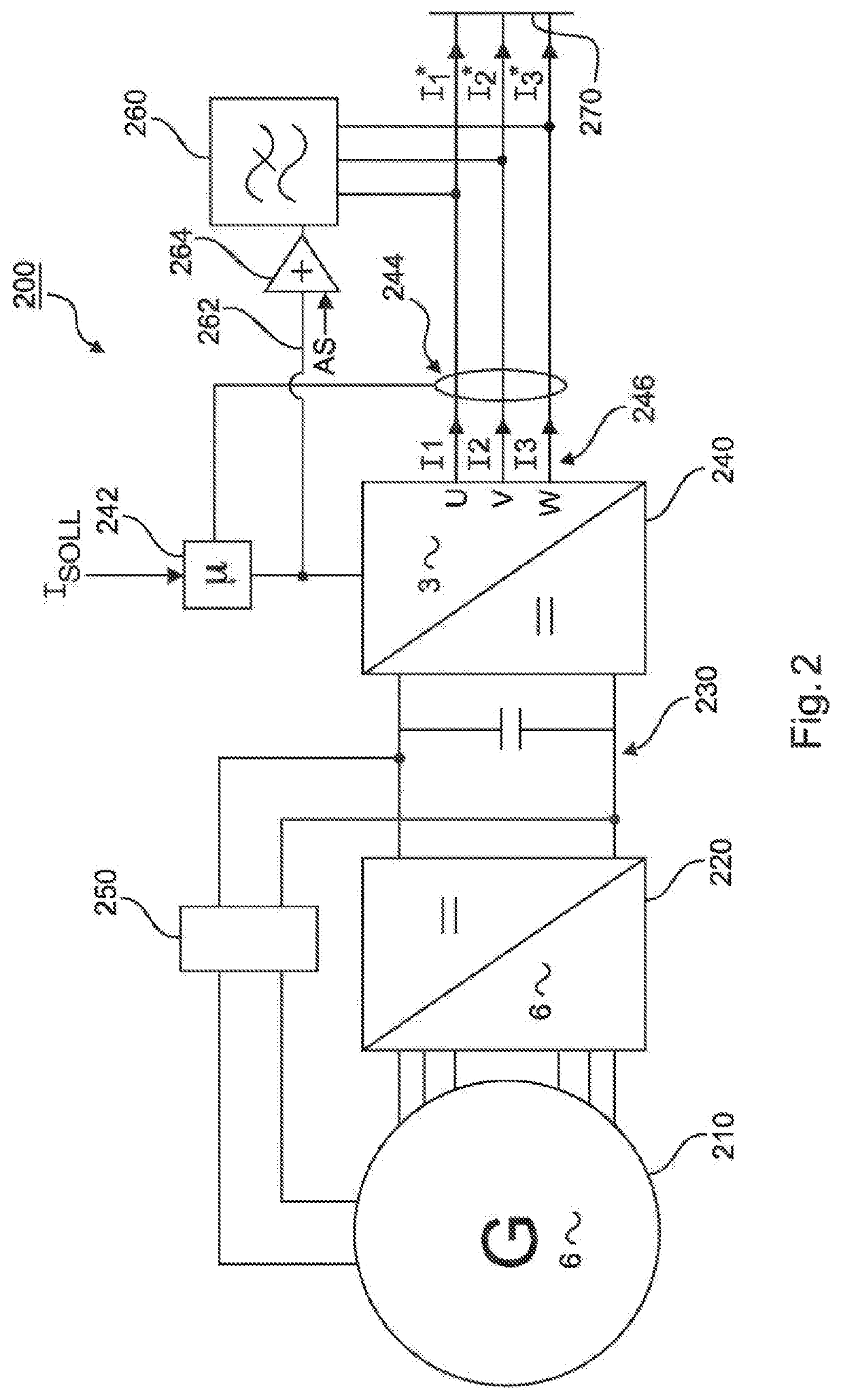
[0084]FIG. 2 shows, in a simplified manner, an electrical section 200 of a wind power installation shown in FIG. 1.

[0085]The electrical section 200 has a 6-phase ring generator 210, which is caused to rotate by the wind by way of a mechanical drive train of the wind power installation in order to generate a 6-phase electrical alternating current.

[0086]The 6-phase electrical alternating current is transferred from the generator 210 to the rectifier 220, which is interconnected with the 3-pha...


PUM


Abstract

A wind power installation and a method for feeding a filtered alternating current into an electrical supply grid by the wind power installation are provided. The wind power installation includes at least one inverter having an inverter output for providing an inverter current. The at least one inverter is coupled at its inverter output to an active filter. The active filter filters the inverter current provided at the inverter output and provides the filtered alternating current for feeding into the electrical supply grid. The method includes providing the inverter current at the inverter output by switching at least one switch of the inverter, sensing the switching, and controlling the active filter based on the sensed switching to filter the inverter current provided at the inverter output and produce the filtered alternating current.

Description

BACKGROUNDTechnical Field[0001]The present invention relates to a method for feeding an electrical alternating current into an electrical supply grid by means of a wind power installation and to a wind power installation which comprises at least one inverter with an inverter output, which is coupled to an active filter.Description of the Related Art[0002]It is particularly known for wind power installations to generate electrical alternating current by using electrical inverters and to a feed electrical alternating current into the electrical supply grid by means of electrical inverters.[0003]For this purpose, wind power installations usually have at least one electrical generator for generating an electrical alternating current. For feeding into the electrical supply grid, the electrical alternating current generated by the generator is then rectified by means of at least one inverter in such a way that the electrical alternating current generated by the generator then meets the re...

Claims


Application Information

Patent Timeline
Patent Type & Authority Patents(United States)
IPC IPC(8): F03D9/00H02P9/04H02M1/12F03D7/00H02J3/38H02M7/5387F03D9/25
CPCH02M1/12F03D7/00H02J3/386H02M7/5387F03D9/255H02J2300/28H02J3/381Y02E10/76Y02E10/72H02J3/06H02J3/01H02J3/38
Inventor HEYEN, CHRISTIAN
Owner WOBBEN PROPERTIES GMBH
Learn More