System and method for high frequency leakage reduction through selective harmonic elimination in electrosurgical generators

a generator and high frequency technology, applied in the field of electrosurgical generators, can solve the problems of high frequency current leakage from the electrosurgical generator through parasitic circuit pathways, circuits are costly, and require significant engineering to be properly implemented, so as to reduce the total leakage current and reduce the amplitude

Active Publication Date: 2017-11-02
UNIV OF TENNESSEE RES FOUND +1
View PDF7 Cites 0 Cited by
  • Summary
  • Abstract
  • Description
  • Claims
  • Application Information

AI Technical Summary

Benefits of technology

[0005]The present disclosure provides an electrosurgical generator including a non-resonant power converter having one or more switching elements controlled by a switching waveform (e.g., a pulse-width modulated waveform) generated by a controller. The switching waveform is calculated using a selective harmonic elimination algorithm to reduce and / or eliminate the amplitude of high-frequency harmonics present in an RF waveform generated by the non-resonant power converter. Higher frequency harmonic waveforms encounter lower impedance through parasitic leakage paths, hence, these waveforms leak more readily than the fundamental or lower harmonic waveforms. Thus, by reducing the amplitude of higher frequency waveforms, the electrosurgical generator according to the present disclosure dramatically reduces total leakage current without affecting power delivered at the fundamental frequency.

Problems solved by technology

During use, high frequency currents may leak from the electrosurgical generators through parasitic circuit pathways due to stray capacitance between components of the electrosurgical generator.
However, conventional electrosurgical generators utilize leakage mitigation circuits, such as leakage chokes, harmonic filters, and low parasitic capacitance components.
These circuits are costly and require significant engineering to be properly implemented within electrosurgical generators.

Method used


Image

  • System and method for high frequency leakage reduction through selective harmonic elimination in electrosurgical generators
  • System and method for high frequency leakage reduction through selective harmonic elimination in electrosurgical generators
  • System and method for high frequency leakage reduction through selective harmonic elimination in electrosurgical generators

Examples


Embodiment Construction

[0021]Particular embodiments of the present disclosure will be described below with reference to the accompanying drawings. In the following description, well-known functions or constructions are not described in detail to avoid obscuring the present disclosure in unnecessary detail. Those skilled in the art will understand that the present disclosure may be adapted for use with any electrosurgical instrument. It should also be appreciated that different electrical and mechanical connections and other considerations may apply to each particular type of instrument.

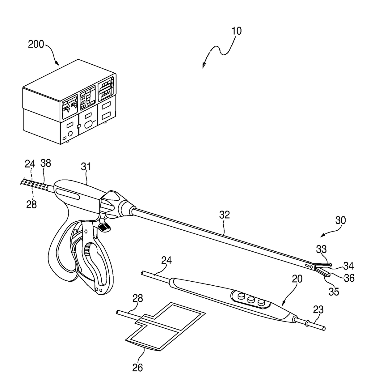
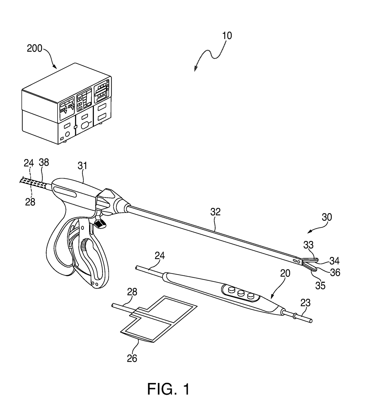
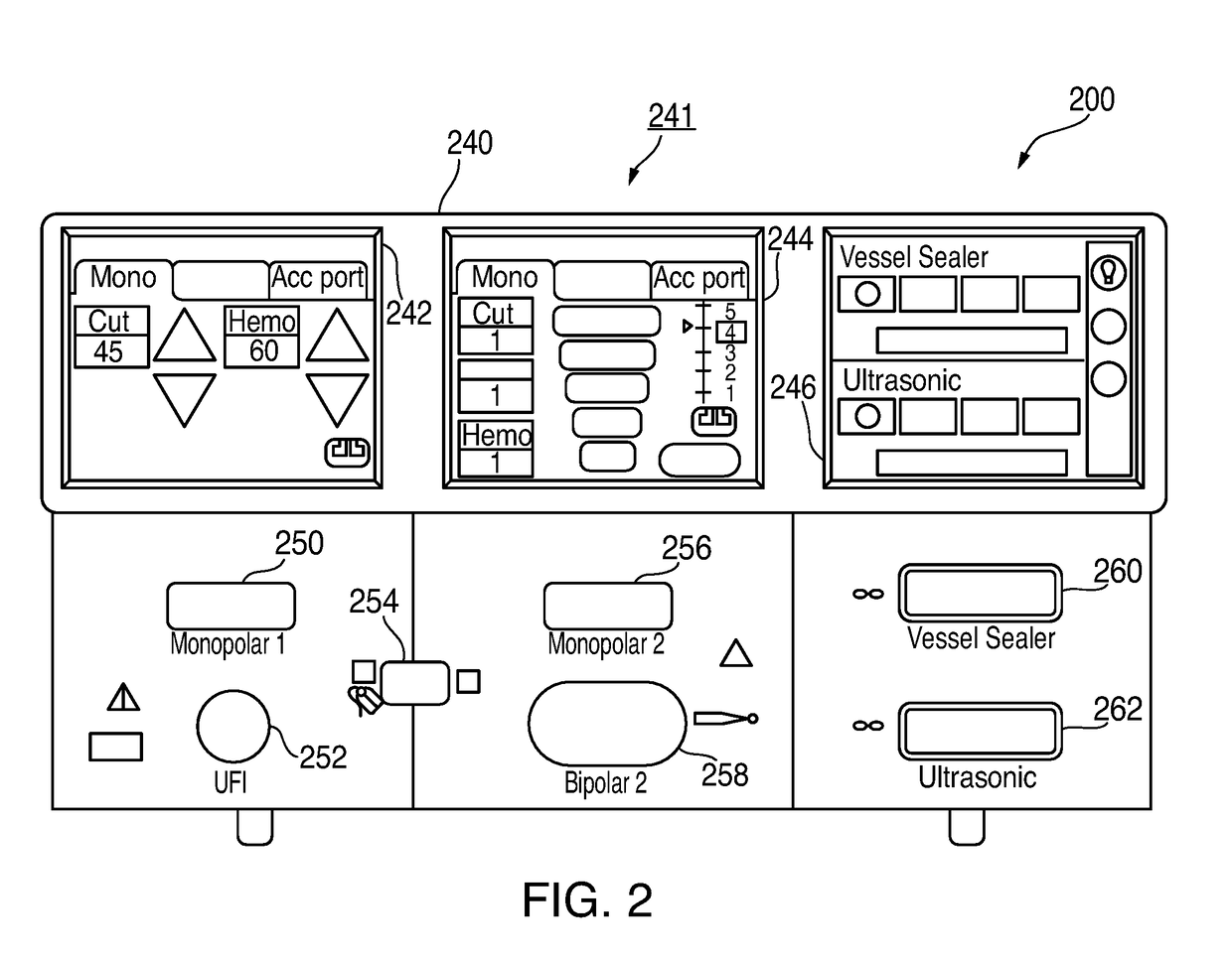
[0022]A generator according to the present disclosure can operate ultrasonic and electrosurgical instruments at multiple frequencies. In particular, the generator may be used in monopolar and / or bipolar electrosurgical procedures, including, for example, cutting, coagulation, ablation, and vessel sealing procedures. The generator may include a plurality of outputs for interfacing with various ultrasonic and electrosurgical ...


PUM


Abstract

An electrosurgical generator includes: a power supply configured to output a DC waveform; an inverter coupled to the power supply, the inverter including a plurality of switching elements; and a controller coupled to the inverter and configured to generate a switching angle waveform including a plurality of switching pulses. The controller is further configured to at least one of select or calculate the plurality of switching pulses to activate the plurality of switching elements to generate a radio frequency waveform based on the DC waveform and to minimize harmonics of the radio frequency waveform.

Description

BACKGROUNDTechnical Field[0001]The present disclosure relates to systems and methods for eliminating or minimizing leakage current in an electrosurgical generator. In particular, the present disclosure relates to an electrosurgical generator configured to reduce the amplitude of high frequency harmonic waveforms, which cause leakage current, using selective harmonic elimination modulation.Background of Related Art[0002]Electrosurgery involves application of high radio frequency (“RF”) electrical current to a surgical site to cut, ablate, desiccate, or coagulate tissue. In monopolar electrosurgery, a source or active electrode delivers radio frequency alternating current from the electrosurgical generator to the targeted tissue. A patient return electrode is placed remotely from the active electrode to conduct the current back to the generator.[0003]In bipolar electrosurgery, return and active electrodes are placed in close proximity to each other such that an electrical circuit is f...

Claims


Application Information

Patent Timeline
Patent Type & Authority Applications(United States)
IPC IPC(8): A61B18/12A61B17/29
CPCA61B18/1206A61B2017/2948A61B17/29A61B18/12A61B18/1233A61B2018/00589A61B2018/00601A61B18/1445A61B2018/00994A61B2018/1266
Inventor FRIEDRICHS, DANIEL A.JOHNSTON, MARK A.COSTINETT, DANIEL J.TRENTO, BRADFORD C.ZHAO, CHONGWEN
Owner UNIV OF TENNESSEE RES FOUND
Why Eureka
Try Eureka