Supercharge Your Innovation With Domain-Expert AI Agents!

Multilayer body that includes piezoelectric body

a piezoelectric body and multi-layer technology, applied in the field of multi-layer bodies, can solve the problem of inability to obtain high sensitivity, and achieve the effect of improving acoustic characteristics and high sensitivity

Active Publication Date: 2021-11-02
PANASONIC INTELLECTUAL PROPERTY MANAGEMENT CO LTD
View PDF16 Cites 0 Cited by
  • Summary
  • Abstract
  • Description
  • Claims
  • Application Information

AI Technical Summary

Benefits of technology

This patent provides a solution for improving the sensitivity of ultrasonic transducers. By using an acoustic matching layer with a plastic foam containing closed pores, the resulting ultrasonic transducer has better acoustic characteristics. This allows for a more efficient and sensitive ultrasonic wave emission. The patent also includes various embodiments that offer different benefits and advantages.

Problems solved by technology

In the related-art ultrasonic transducer, because matching of acoustic impedance between the acoustic matching layer and a medium to which the ultrasonic wave is emitted is not sufficient, high sensitivity cannot be obtained.

Method used


Image

  • Multilayer body that includes piezoelectric body
  • Multilayer body that includes piezoelectric body
  • Multilayer body that includes piezoelectric body

Examples


first embodiment

[0054]Examples of the ultrasonic transducer and the ultrasonic flowmeter according to a first embodiment will be described in detail below.

Configuration of Ultrasonic Flowmeter

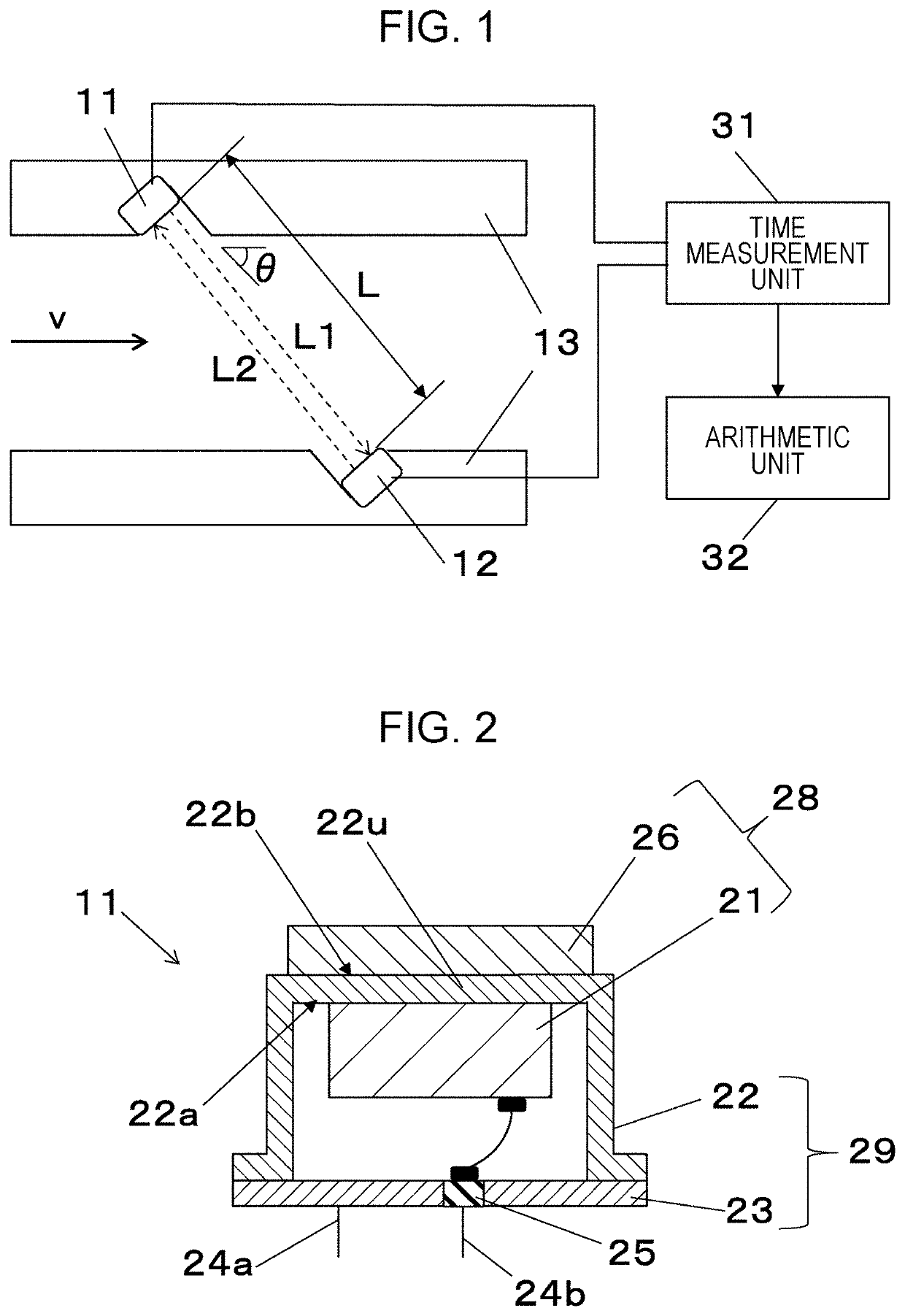
[0055]FIG. 1 is a block diagram of an embodiment of an ultrasonic flowmeter according to the present disclosure. As illustrated in FIG. 1, the ultrasonic flowmeter includes a flow passage through which a fluid to be measured flows, a pair of ultrasonic transducers 11 and 12 disposed in the flow passage, a time measurement unit 31, and an arithmetic unit 32. The fluid flows through the flow passage, which is defined by a pipe wall 13, at a flow velocity V in a direction denoted by an arrow in the drawing. A flow rate of the fluid flowing through the flow passage is measured. The pair of ultrasonic transducers (first and second ultrasonic transducers) 11 and 12 are disposed at the pipe wall 13 in an opposing relation. Each of the ultrasonic transducers 11 and 12 includes a piezoelectric vibrator made of a piezoe...

second embodiment

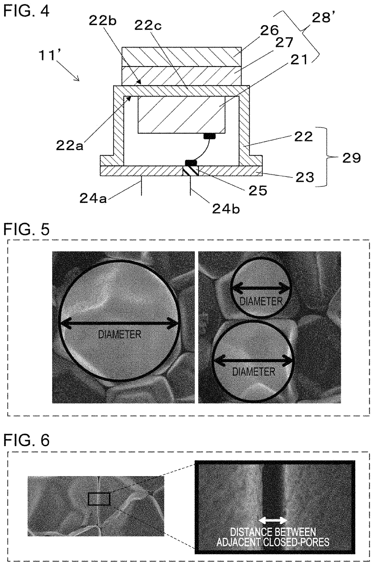
[0077]FIG. 4 illustrates a schematic structure of an ultrasonic transducer used in an ultrasonic flowmeter according to a second embodiment. In FIG. 4, the same or similar components as or to those in the first embodiment illustrated in FIG. 1 are denoted by the same reference signs. Description of the same or similar components as or to those in the first embodiment is omitted in some cases. The ultrasonic transducer illustrated in FIG. 4 is different from that in the first embodiment in including a multilayer body 28′ which includes the piezoelectric body 21, the first acoustic matching layer 26, and a second acoustic matching layer 27.

[0078]The second acoustic matching layer 27 is positioned between the piezoelectric body 21 and the first acoustic matching layer 26. In this embodiment, the second acoustic matching layer 27 is bonded to the outer surface 22b of the top plate 22u, and the first acoustic matching layer 26 is in contact with the second acoustic matching layer 27. The...

examples

[0082]The following description is made about processes of fabricating the ultrasonic transducers and the ultrasonic flowmeters according to the first and second embodiments, and results of checking characteristics thereof.

1. Preparation of Samples

Reference Example (A)

(a) Production of Second Acoustic Matching Layer (Silica Porous Body)

[0083]A spherical acrylic resin having a diameter of several ten μm and a sintered silica powder having a diameter of not more than 1 μm were mixed together and then molded under pressure. A resulting molding was dried and fired at 900° C., whereby a silica porous body was obtained. Thereafter, the second acoustic matching layer was obtained by adjusting the thickness of the silica porous body to be ¼ of the oscillation wavelength of an ultrasonic wave. The acoustic velocity of the ultrasonic wave of about 500 kHz propagating in the second acoustic matching layer was 1500 m / s. The second acoustic matching layer had a density of 570 kg / m3 and a thickne...


PUM

PropertyMeasurementUnit
densityaaaaaaaaaa
densityaaaaaaaaaa
pore sizeaaaaaaaaaa

Abstract

A multilayer body includes a piezoelectric body and a first acoustic matching layer in direct or indirect contact with the piezoelectric body. The first acoustic matching layer includes a plastic foam containing a plurality of closed pores. An average pore size of the closed pores is not smaller than 1 μm and not larger than 100 μm. The first acoustic matching layer has a density of not less than 10 kg / m3 and not more than 100 kg / m3.

Description

BACKGROUND1. Technical Field[0001]The present disclosure relates to a multilayer body including a piezoelectric body and an acoustic matching layer, an ultrasonic transducer, and an ultrasonic flowmeter.2. Description of the Related Art[0002]Recently, an ultrasonic flowmeter for measuring a time taken for an ultrasonic wave to travel through a propagation path, determining a moving speed of a fluid, and calculating a flow rate of the fluid has been utilized in gas meters, etc. In general, the ultrasonic flowmeter includes a piezoelectric vibrator, and detects an ultrasonic wave using the piezoelectric vibrator. In the case of the fluid being gas, because a difference in acoustic impedance between the gas and the piezoelectric vibrator is large, the ultrasonic wave propagating through the gas tends to be reflected at the interface between the piezoelectric vibrator and the gas. Taking into account the above point, an acoustic matching layer is often disposed at the interface between ...

Claims


Application Information

Patent Timeline
Patent Type & Authority Patents(United States)
IPC IPC(8): G01F1/66G10K11/02H04R17/00B06B1/06
CPCG01F1/662B06B1/067B06B1/0607G10K11/02H04R17/00B06B2201/70
Inventor SUGAYA, HIDETAKAMASUDA, TOMOKINAGAHARA, HIDETOMO
Owner PANASONIC INTELLECTUAL PROPERTY MANAGEMENT CO LTD
Features
  • R&D
  • Intellectual Property
  • Life Sciences
  • Materials
  • Tech Scout
  • Unparalleled Data Quality
  • Higher Quality Content
  • 60% Fewer Hallucinations
Learn More