Hydroponic growth system

Active Publication Date: 2021-11-09
DIEHL PATRICK ALLAN
View PDF13 Cites 2 Cited by
  • Summary
  • Abstract
  • Description
  • Claims
  • Application Information

AI Technical Summary

Benefits of technology

[0005]The invention, disclosed herein, addresses the above-mentioned need for a device, which offers maximum productivity with minimum space requirements. Furthe

Problems solved by technology

Although several existing devices have attempted to address the above-mentioned need, most have failed to provide a complete and inexpensive solutio

Method used


Image

  • Hydroponic growth system
  • Hydroponic growth system
  • Hydroponic growth system

Examples


Example

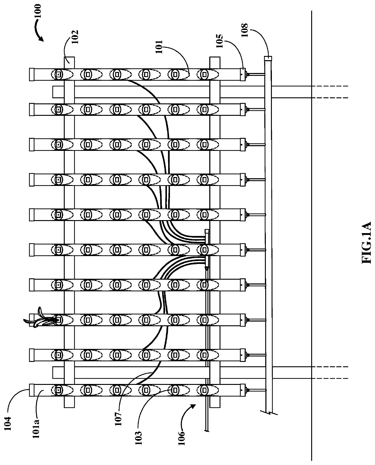
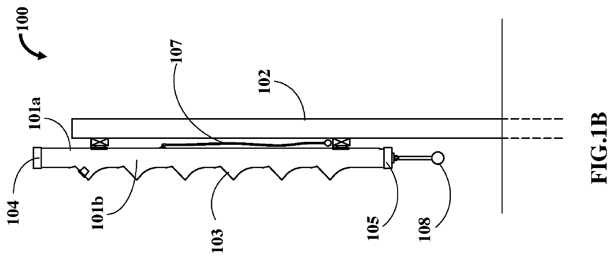
[0015]FIG. 1A exemplarily illustrates a front elevation view of a hydroponic growth system 100 mounted on a support assembly. FIG. 1B exemplarily illustrates a right-side elevation view of a hydroponic growth system 100. The hydroponic growth system 100 comprises a plurality of grow tubes 101 mounted on a support assembly 102. The support assembly 102 is shown as a frame member capable of bearing the load applied by the grow tubes 101. In different embodiments of the present invention, several types of support assemblies 102 may be used based on space requirements or other functional requirements. In the present disclosure, only two such embodiments have been discussed in detail. As used herein, “grow tubes” refer to hollow tubular structures configured to support and nourish a plurality of plants. The grow tubes 101 are of a generally hollow cylindrical configuration. However, it may be appreciated several other configurations, for example, hollow cuboidal, hollow elliptical, etc.,...


PUM


Abstract

A hydroponic growth system comprises grow tubes and a misting assembly. Each of the grow tubes, of a generally hollow cylindrical configuration, are mounted vertically on a support assembly and comprise openings configured on an outer surface of the grow tube for receiving receptacles containing plants. Each of the grow tubes comprise a top vent and a bottom vent. The misting assembly comprises spray tubes inserted into a middle section of the grow tubes to distribute and spray a nutrient solution into an inner surface of each of the grow tubes. The nutrient solution is absorbed by roots of the one or more plants extending into the inner surface of the grow tubes. Unused nutrient solution is drained into a sump positioned beneath the grow tubes via the bottom vents and recirculated within the misting assembly for spraying the nutrient solution to grow the plants.

Description

I. BACKGROUND OF THE INVENTION1. Field of the Invention[0001]The present disclosure generally relates to hydroponic systems. More particularly, the present disclosure relates to a hydroponic growth system including a plurality of grow tubes with a reusable water circuit.2. Description of the Related Art[0002]Hydroponics refers to a method of growing plants without soil. Existing devices have been used to ensure plant growth using hydroponics. Typically, a nutrient rich solution is supplied to several receptacles containing one or more plants. With increasing population and the reducing availability of arable land, it is highly essential that productivity of such devices be increased with minimum increase in use of land and other resources. Although several existing devices have attempted to address the above-mentioned need, most have failed to provide a complete and inexpensive solution. For instance, U.S. Pat. No. 4,622,777 issued to George J. Greene discloses a rotatable planter i...

Claims


Application Information

Patent Timeline
IPC IPC(8): A01G31/06A01G31/00
CPCA01G31/06A01G2031/006A01G9/023Y02P60/21
Inventor DIEHL, PATRICK ALLAN
Owner DIEHL PATRICK ALLAN
Why Eureka
Try Eureka