
Tracking techniques in haptic systems

a technology of haptic systems and tracking techniques, applied in the field of improved techniques of hand tracking within haptic systems, can solve the problems of reducing the ability to work in sync with other techniques for hand tracking, limiting the use of hand tracking successfully, and further limiting the resolution and accuracy of hand tracking

Active Publication Date: 2021-11-09
ULTRALEAP LTD
View PDF233 Cites 18 Cited by
  • Summary
  • Abstract
  • Description
  • Claims
  • Application Information

AI Technical Summary

Benefits of technology

This approach enables accurate detection of object presence and location estimation without the need for multiple receivers, reducing hardware and computational costs, and allows for object tracking in scenarios where traditional methods fail, providing robust hand tracking and gesture recognition capabilities.

Problems solved by technology

Thus, their use in successfully tracking the hand is limited; restricted to the uniquely generated acoustic fields specified in the abovementioned documents.
Their performance, resolution and accuracy in hand tracking is further limited by certain conditions applied to the generated acoustic fields, reducing their ability to work in synergy with other techniques for hand tracking.
Finally, none of the above approaches handle the task of detecting the absence or presence of a hand above the array.
Although the mentioned techniques can be used for acoustic tracking of an object, e.g. a bare hand, they suffer fundamental limitations.
Although the above proposed novel methodology can determine the presence and absence of an object and identify its coarse location in terms of the specific quadrant, this is done at the cost of using a reduced set of transmitting elements.
In addition, the domain of identification may be limited within the area of a 16×16 cm space corresponding to the array aperture.
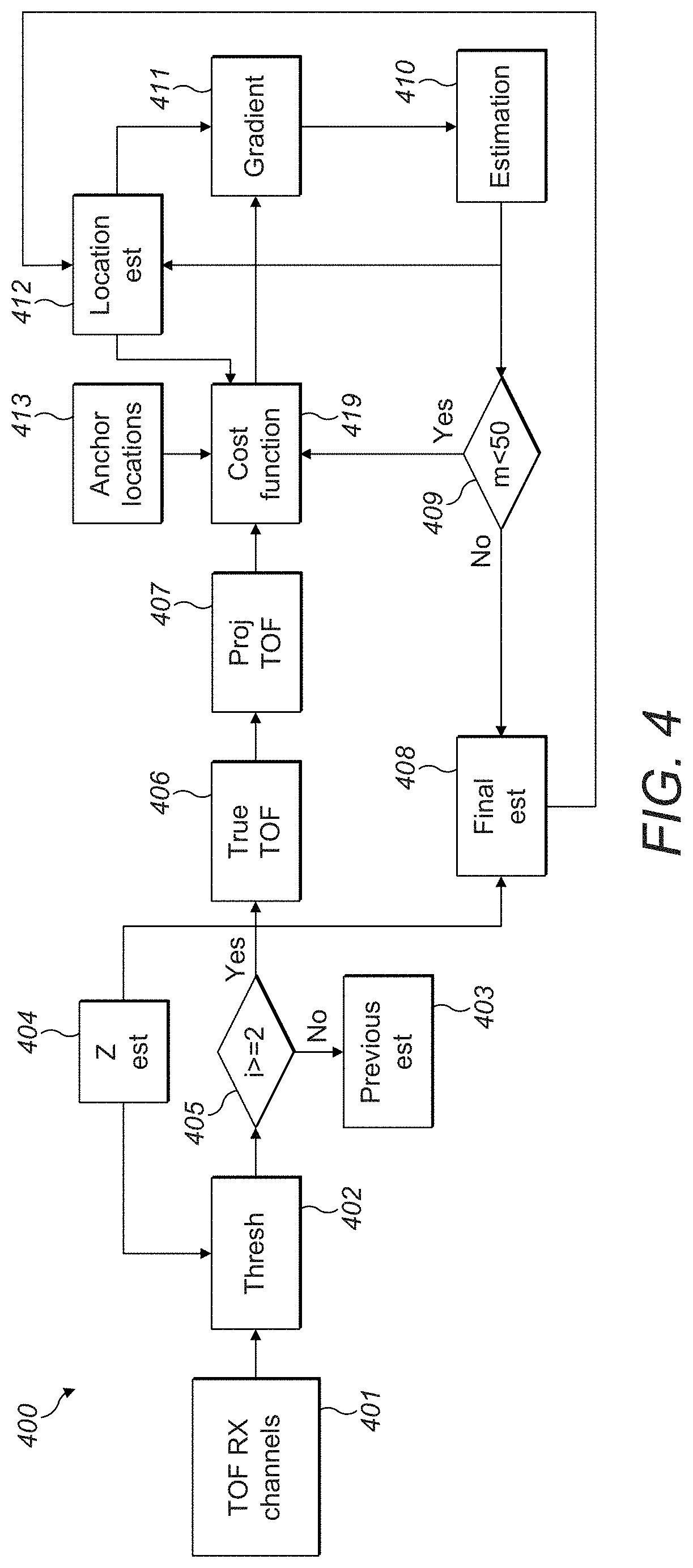
A potential drawback is that any noise and inaccuracies in the estimation of the first dimension with basic TOF would lead to noisy estimations for the remaining coordinates.
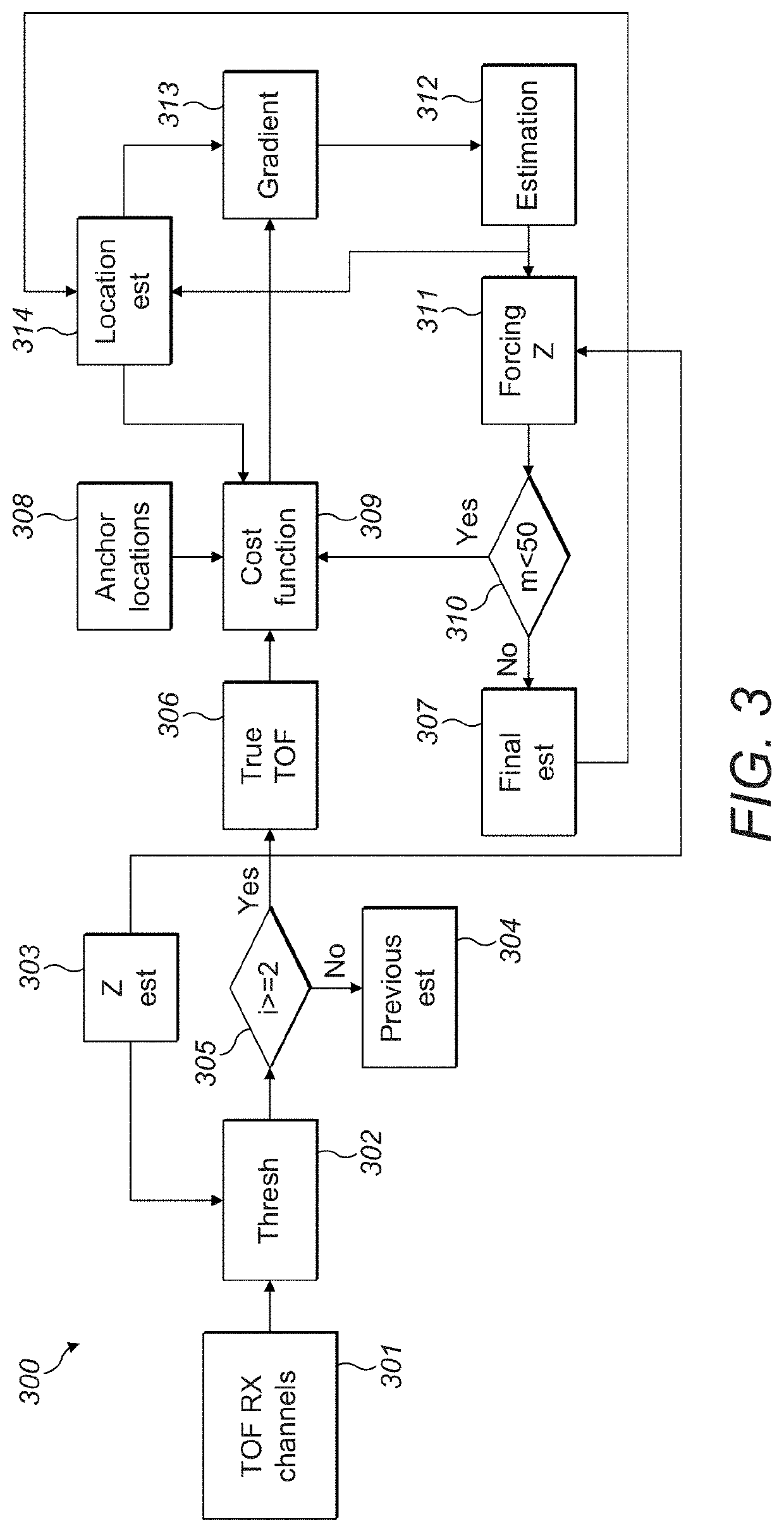
Weighting the distance measurements according to the confidence of each anchor node limits the effect of measurement error and increase the signal-to-noise-ratio of the estimation.
This demonstrates that if classical approach is utilized 610, the algorithm cannot find the global minimum, as the gradient is uncontrolled and not converging in the time.

Method used


Image

  • Tracking techniques in haptic systems
  • Tracking techniques in haptic systems
  • Tracking techniques in haptic systems

Examples


Embodiment Construction

[0027]I. Coarse Estimation of the (x,y) Sub-Space for Hand Tracking

[0028]The proposed techniques aim at reducing the (x,y) domain where the object would be located to a reduced sub-space (quadrant). Either the correlation coefficient or the covariance calculations are used as a means to determine the lack of signal dependency or a strong signal dependency. Consequently, the absence or presence of the object can be determined respectively in one of the four quadrants. In addition, mapping the information of the index of the selected quadrant into specific (x,y) coordinate values is also considered.

[0029]A. Simplified Approach

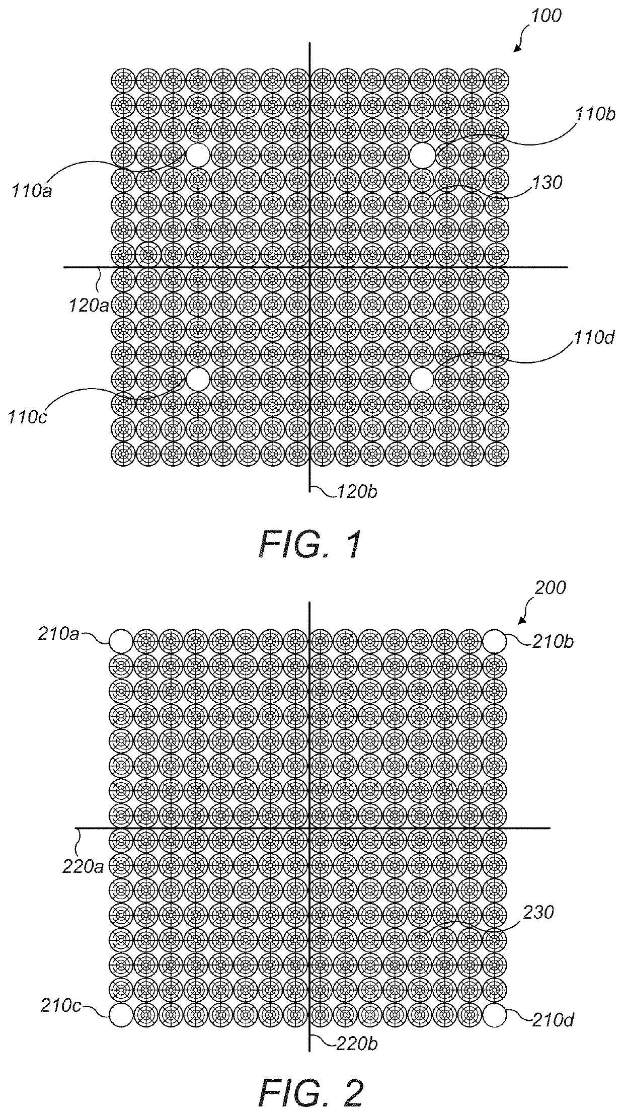
[0030]Turning to FIG. 1, shown is a schematic 100 of an array of transducers 130 divided into four equivalent areas as marked by the intersecting lines 120a, 120b, creating quadrants. Each quadrant contains a receiving element as marked by the white dots 110a, 110b, 110c, 110d surrounded by transmitting elements. The broader assumption here is that each receiver ...


PUM


Abstract

A method for object tracking is presented based on the similarity of waveforms recorded at the receiving elements of the array. A rectangular array of acoustic transducers is divided into four quadrants, on the basis that each quadrant contains a receiving element in its center. Each of the four recorded waveforms are compared against each of the remaining waveforms to identify either absolute similarity of the signal characteristics, which would denote absence of the object, or identifying a waveform being the least similar from the rest, hence pointing to a part of the array above which the object is located. Further, source localization algorithms are used for ill-posed scenarios where the distance between receivers is on the same order of magnitude of the dimensions of the tracked object and of the tracking distances.

Description

PRIOR APPLICATIONS[0001]This application claims the benefit of: (1) U.S. Provisional Patent Application No. 62 / 932,925 filed on Nov. 8, 2019; and (2) U.S. Provisional Patent Application No. 62 / 933,609, filed on Nov. 11, 2019, both of which are incorporated by reference in its entirety.FIELD OF THE DISCLOSURE[0002]The present disclosure relates generally to improved techniques in tracking within haptic systems consisting of transducer arrays.BACKGROUND[0003]An array of transducers can be used to create a continuous acoustic field, in the form of a distribution of sound energy. This field can have a number of applications including but not limited to generation of haptics in mid-air, haptic feedback and object levitation in air.[0004]The acoustic field can be controlled through spatial points (the control points), to which an amplitude and phase value are assigned. The aforementioned array of transducers can then be used to define and generate the acoustic field which will exhibit the...

Claims


Application Information

Patent Timeline
Patent Type & Authority Patents(United States)
IPC IPC(8): G06F3/01G06F3/0488
CPCG06F3/016G06F3/017G06F3/04883G06F3/0436G10K11/346G10K11/348
Inventor SARAFIANOU, MANTALENAIODICE, MICHELEJIBRY, RAFEL
Owner ULTRALEAP LTD
Learn More