
Rotatable shadowband

a shadowband and rotational technology, applied in the field of rotational shadowbands, can solve the problems of systematic underestimation of diffuse solar radiation, difficult to take into account the effect, and difficult to observe the effect of diffuse solar radiation

Active Publication Date: 2021-11-16
IMAM ABDULRAHRNAN BIN FAISAL UNIVERSITY
View PDF11 Cites 0 Cited by
  • Summary
  • Abstract
  • Description
  • Claims
  • Application Information

AI Technical Summary

Benefits of technology

The patent describes a device that can shade a pyranometer using a rotating shadowband. The device has a support structure with a base, top surface, hollow interior, and side walls. It also includes a cylindrical ring connected to the top surface, a semicircular shadowband held by the ring, and a motor for rotating the shadowband. The semicircular shadowband can be opened and closed to alternatively shade and expose the pyranometer from sunlight. The device can be powered by a battery and is controlled by a controller. The technical effects of the invention are to provide a tool to measure sunlight accurately, even when the sun is moving, and to protect the pyranometer from damage.

Problems solved by technology

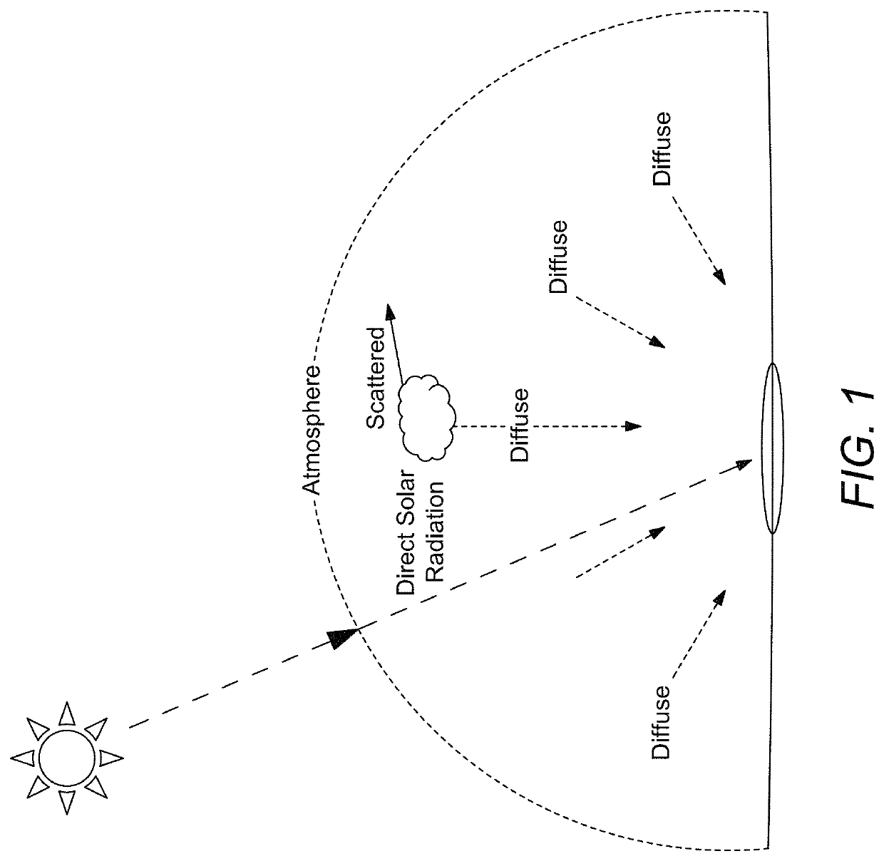
The major disadvantage is the systematic underestimation of diffuse solar radiation as a result of the blocking effect caused by the ring.
This effect is difficult to take into consideration because it depends not only on the geometrical characteristic of the device, but also on the hemispherical distribution of solar radiation.
The combination of these two factors makes the measurements of diffuse solar radiation an observational challenge.
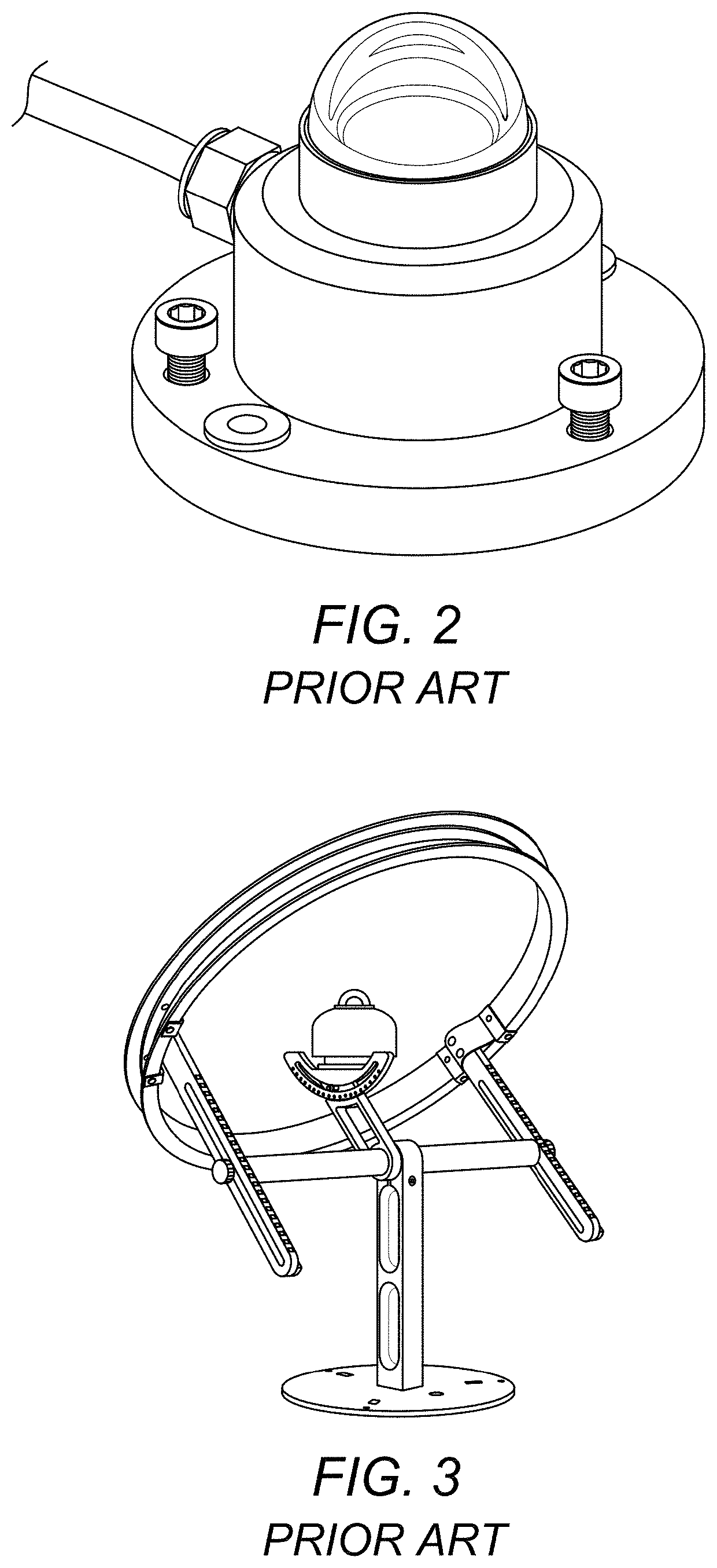
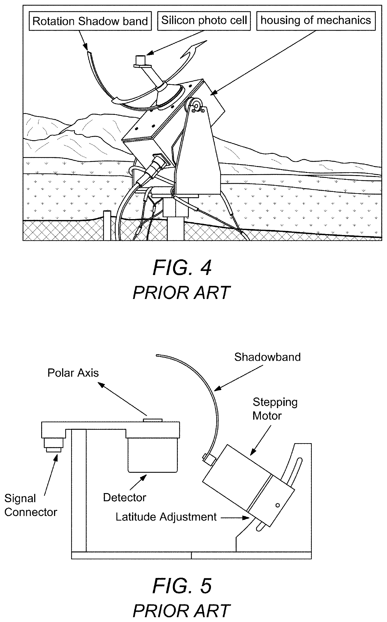
The diffuse radiation measuring devices above lack ruggedness in the field and may require mathematical correction for the solar irradiance volume blocked by the shadow ring.

Method used


Image

  • Rotatable shadowband
  • Rotatable shadowband
  • Rotatable shadowband

Examples


first embodiment

[0094]Alternatively, the first embodiment may include a frameless brushless DC motor 1252 having a rotor and a stator; and where the stator is connected to the top surface of the support and the rotor is connected to the first cylindrical ring concentric with the axis of the first cylindrical ring, the motor energizing the stator to rotate the rotor, which rotates the first cylindrical ring as shown in FIG. 12C.

[0095]In another alternative illustrated in FIG. 13A-13C, the first embodiment may include that the first cylindrical ring 1314 has a thickness, a central axis parallel to the thickness, a diameter, a radially inner surface and a radially outer surface and a first and second channel extending perpendicularly to the central axis from the radially outer surface to the radially inner surface, wherein the first and second channels are linearly aligned with the diameter of the first cylindrical ring, wherein each bracket 1319 includes a hole perpendicular to the thickness of the b...

second embodiment

[0101]A second embodiment is illustrated with respect to claims 8-20 and describes a system for rotating a shadowband 810, comprising rotating, with a motor 1252 connected to a power source (1262, 1248 or 1260), a shadowband within a first cylindrical ring 814.

[0102]The shadowband may include a window opening 910 as shown in FIG. 9A, wherein rotating the shadowband alternately shades and exposes a pyranometer to direct sunlight.

[0103]Next, further details of the hardware description of the controller of FIG. 15 according to exemplary embodiments are described with reference to FIG. 16. In FIG. 16, a controller 1600 is described is representative of the control system 1570 of FIG. 15 in which the controller is a computing device which includes a CPU 1601 which performs the processes described above / below. The process data and instructions may be stored in memory 1602. These processes and instructions may also be stored on a storage medium disk 1604 such as a hard drive (HDD) or porta...


PUM


Abstract

A rotating shadowband for shading a pyranometer includes a cylindrical ring and a semicircular shadowband held within the cylindrical ring, a motor configured for rotating the shadowband, at least one solar panel, a rechargeable battery, and a controller having circuitry configured to power the first motor to rotate the semicircular shadowband. The semicircular shadowband may include a window opening, wherein the window opening substantially extends from a center of the band to a first end. The controller rotates the shadowband 0 to 360 degrees about the central axis of the cylindrical ring to alternately shade the pyranometer for making diffuse radiation measurements and expose the pyranometer to direct solar radiation for making global radiation measurements. Alternatively, the shadowband may be solid and rotate pivotally 0 to 180 degrees or 0 to 360 degrees within the cylindrical ring to alternately shade and expose a pyranometer head to and from direct sunlight respectively.

Description

BACKGROUNDTechnical Field[0001]The present disclosure is directed to a rotatable shadowband for shielding a pyranometer head or a lighting sensor from direct solar radiation during diffuse radiation measurements.Description of Related Art[0002]The “background” description provided herein is for the purpose of generally presenting the context of the disclosure. Work of the presently named inventors, to the extent it is described in this background section, as well as aspects of the description which may not otherwise qualify as prior art at the time of filing, are neither expressly or impliedly admitted as prior art against the present invention.[0003]The sun's radiation on the earth is referred to as global solar radiation. Sometimes called short-wave radiation, when measured global solar radiation is a combination of direct and diffuse solar radiation received from the hemisphere above the plane of a measuring instrument. Direct radiation is the radiation that comes directly from t...

Claims


Application Information

Patent Timeline
IPC IPC(8): G01S3/786G01W1/10G01J1/06G01J1/42
CPCG01S3/7861G01J1/06G01W1/10G01J2001/4285G01J1/0271G01J1/0403G01J1/0437G01J1/42G01W1/12
Inventor ALSHAIBANI, KHALID ASKER
Owner IMAM ABDULRAHRNAN BIN FAISAL UNIVERSITY
Learn More