Passive repeater device, microwave network, and method of designing a repeater device

a repeater device and microwave network technology, applied in the field of passive repeater devices, can solve problems such as network slowness, video quality degrade, video freeze,

Active Publication Date: 2021-11-16
3M INNOVATIVE PROPERTIES CO
View PDF17 Cites 1 Cited by
  • Summary
  • Abstract
  • Description
  • Claims
  • Application Information

AI Technical Summary

Problems solved by technology

When one or many of these impairments affects the wireless channel, one or more problems may arise (e.g., the video quality degrades, the video freezes, the internet page the subscriber wants to access fails to load, and the network is slow).
These various issues lead to subscriber dissatisfaction and turnover.
Sub-6 GHz bands available for small cell backhaul have narrow bandwidth and may not enable small cell backhaul data rates greater than 1 Gbps.
However in some cases, fiber may not be available at a particular location and city ordinances may prohibit trenching to pull fiber to the small cell location.
However still, a clear line of sight may not be available between the small cell backhaul antenna and the remote base station antenna.
Unfortunately, higher frequencies suffer from increased propagation path loss; high shadowing path loss due for example to building blockage, trees, and other obstructions; and higher oxygen and water absorption.
Yet, in dense urban environment, the path between the rooftop access point where the cellular rooftop site is located and the mobile users at the street level may be blocked by another building or other obstacles, in such a way that there is no direct line of sight between the rooftop antenna and the mobile users.
In these conditions, the mmWave link data rate will be severely degraded.

Method used


Image

  • Passive repeater device, microwave network, and method of designing a repeater device
  • Passive repeater device, microwave network, and method of designing a repeater device
  • Passive repeater device, microwave network, and method of designing a repeater device

Examples


embodiments

[0108]Various embodiments are provided.

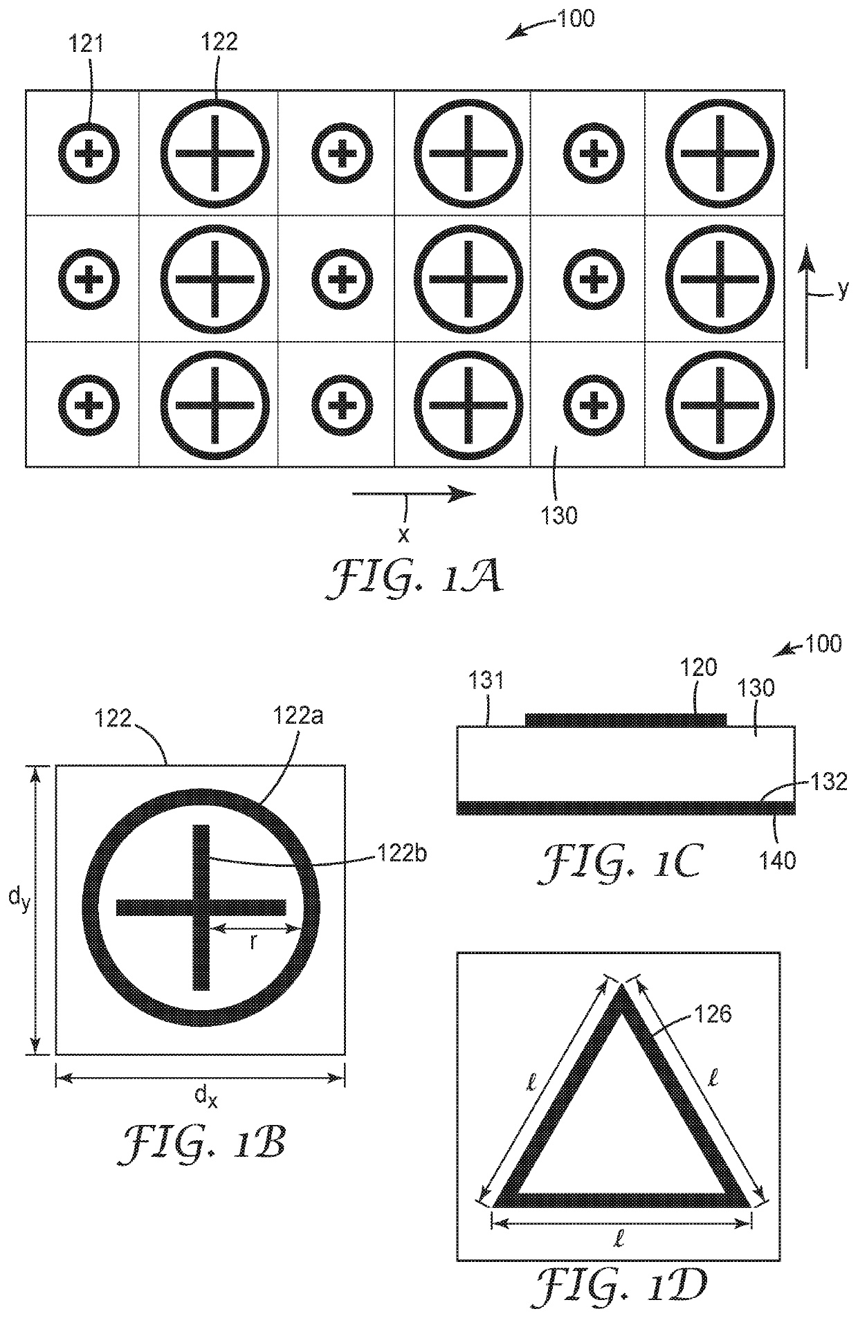
[0109]Embodiment 1A is a repeater device comprising a periodic array of alternating metallic phase shifting elements, the array being periodic in at least one axis, formed on a first surface of a dielectric substrate, with an opposite surface of the dielectric substrate having a ground plane formed thereon, wherein each phase shifting element provides from 0° to 360° phase shifting in the microwave frequency range.

[0110]Embodiment 2A is the repeater device of embodiment 1A, wherein a first phase shifting element includes a first two-dimensional geometric structure and a second phase shifting element includes a second two-dimensional geometric structure, wherein the first and second two-dimensional geometric structures each have a similar shape, and wherein the first two-dimensional geometric structure has a different size than the second two-dimensional geometric structure.

[0111]Embodiment 3A is the repeater device of embodiment 1A, wherein the...


PUM

PropertyMeasurementUnit
frequencyaaaaaaaaaa
frequencyaaaaaaaaaa
frequenciesaaaaaaaaaa

Abstract

A repeater device comprises a periodic array of alternating metallic phase shifting elements, the array being periodic in at least one axis, formed on a first surface of a dielectric substrate, with an opposite surface of the dielectric substrate having a ground plane formed thereon, wherein each phase shifting element provides from 0° to 360° phase shifting in the microwave frequency range. The repeater device can be utilized in a microwave network.

Description

BACKGROUNDField of the Invention[0001]The present invention is directed to a passive repeater device comprising a periodic array of phase shifting elements that can be utilized in a microwave network.Related Art[0002]Modern cellular networks comprise geographic areas of wireless signal coverage called macrocells. Within a macrocell, a base station enables cellular subscribers to connect to the core network and to communicate with other users or to access information on remote servers. With the availability and low cost of smartphones and portable computers, the volume of mobile data traffic on wireless networks is projected to continue to increase over the next several years. The increase in mobile data traffic is driven by bandwidth intensive high resolution video applications and services such as video content sites, gaming, and data, in addition to plain old voice communication.[0003]When data, and particularly video, is transferred over a wireless channel, the quality of the rec...

Claims


Application Information

Patent Timeline
Patent Type & Authority Patents(United States)
IPC IPC(8): H01Q15/14H01Q3/46H04B7/145
CPCH01Q15/148H01Q3/46H04B7/145H04B7/15528
Inventor YEMELONG, CONSTAND E.LEBLANC, STEPHEN P.KING, STEPHEN C.
Owner 3M INNOVATIVE PROPERTIES CO
Why Eureka
Try Eureka