Power conversion apparatus with oscillation reduction control, oscillation reduction control module, and method of operating the same

a technology of oscillation reduction control and power conversion apparatus, which is applied in the direction of power conversion systems, dc-dc conversion, climate sustainability, etc., can solve the problems of insufficient precision, limited suppression effect, and insufficient electromagnetic interference in the mid-frequency band of electromagnetic interference (emi), so as to reduce the amplitude of resonance voltage, accurately control the damping parameters, and delay time

Active Publication Date: 2021-11-16
ASIAN POWER DEVICES
View PDF25 Cites 0 Cited by
  • Summary
  • Abstract
  • Description
  • Claims
  • Application Information

AI Technical Summary

Benefits of technology

[0025]The main purpose and effect of the present disclosure is to use the oscillation reduction control module to detect whether the winding voltage generates the resonance voltage, and when the winding voltage generates the resonance voltage, the damper is provided to rapidly and significantly decay the amplitude of the winding voltage in one resonance period without gradually decaying in the underdamping manner. By reducing the amplitude of the resonance voltage, the electromagnetic interference (EMI) of the power conversion apparatus is reduced so that the power conversion apparatus meets safety standards in the full frequency band.
[0026]In addition, the oscillation reduction control module has the programmable design, which can accurately control the damping parameters and delay time, and even has functions of light-load frequency hopping and shutdown, further no external passive components, such as resistors or capacitors are required. Moreover, based on the similar pin as the primary-side controller of the transformer, the oscillation reduction control module can be integrated into the secondary-side controller. The circuit parameters can be set and burned by the digital controller and the features of high confidentiality and common circuit design so it can be planned to apply different damping parameters under different load conditions to achieve the advantages of both high efficiency and EMI suppression.

Problems solved by technology

The resonance generates a resonance voltage, and the frequency of the resonant voltage is between hundreds of kHz and 10 MHz, which may cause the mid-frequency band of the electromagnetic interference (EMI) to exceed the safety regulations.
The traditional solution is to install an RC damping shock absorber on the primary side of the transformer to absorb the amplitude of the resonance voltage, but the effect of this solution is not precise enough and the suppression effect is limited.
In addition, power will continue to be consumed during the operation of the flyback converter, resulting in poor efficiency of the flyback converter.

Method used


Image

  • Power conversion apparatus with oscillation reduction control, oscillation reduction control module, and method of operating the same
  • Power conversion apparatus with oscillation reduction control, oscillation reduction control module, and method of operating the same
  • Power conversion apparatus with oscillation reduction control, oscillation reduction control module, and method of operating the same

Examples


Embodiment Construction

[0038]Reference will now be made to the drawing figures to describe the present disclosure in detail. It will be understood that the drawing figures and exemplified embodiments of present disclosure are not limited to the details thereof.

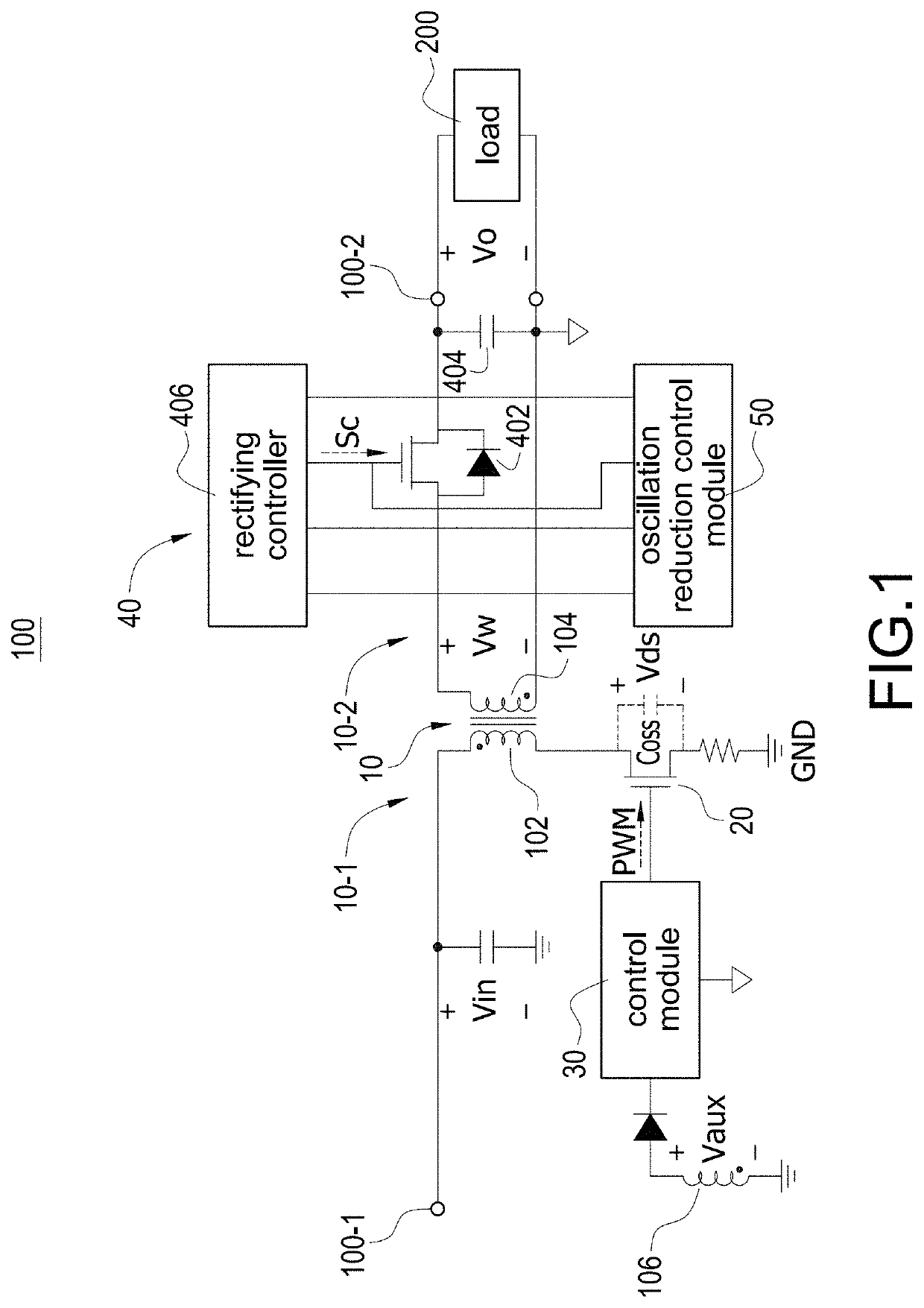
[0039]Please refer to FIG. 1, which shows a block circuit diagram of a power conversion apparatus with oscillation reduction according to the present disclosure. The power conversion apparatus 100 receives an input voltage Vin through an input end 100-1 and provides an output voltage Vo through an output end 100-2 to supply power to a load 200. The power conversion apparatus 100 includes a transformer 10, a power switch 20, a control module 30, a rectifying module 40, and an oscillation reduction control module 50. The transformer 10 has a primary side 10-1 and a secondary side 10-2. The primary side 10-1 includes a primary-side winding 102, and one end of the primary-side winding 102 receives the input voltage Vin through the input end 100-1 and th...


PUM


Abstract

A power conversion apparatus with oscillation reduction control supplies power to a load through an output end. The power conversion apparatus includes a transformer, a power switch, a control module, and an oscillation reduction control module. A primary side of the transformer receives an input voltage, and a secondary side of the transformer is coupled to the output end. The power switch is coupled to the primary side. The control module is coupled to the power switch, controls the power switch continuously turning on and turning off, and converts the input voltage into an output voltage. When the oscillation reduction control module detects a resonance voltage through the secondary side, the oscillation reduction control module performs an oscillation reduction operation to the resonance voltage to reduce an amplitude of the resonance voltage by a damper.

Description

BACKGROUNDTechnical Field[0001]The present disclosure relates to a power conversion apparatus with oscillation reduction control, an oscillation reduction module, and a method of operating the same, and more particularly to a power conversion apparatus with oscillation reduction control, an oscillation reduction module, and a method of operating the same to reduce EMI.Description of Related Art[0002]The statements in this section merely provide background information related to the present disclosure and do not necessarily constitute prior art.[0003]Since an input end and an output end of a flyback converter can be electrically isolated by a transformer and can be used for power delivery (PD) control, the demand for flyback converters is rapidly increasing. In particular, flyback converters can be used for step-up conversion or step-down conversion of electric power. Therefore, in the case of flexible power configuration, flyback converters have increasingly become the mainstream co...

Claims


Application Information

Patent Timeline
Patent Type & Authority Patents(United States)
IPC IPC(8): H02M3/335H02M1/14H02M1/44H02M5/293
CPCH02M3/33507H02M1/143H02M1/44H02M3/33592H02M5/293H02M1/15Y02B70/10
Inventor YAU, YEU-TORNGHUNG, TSUNG-LIANG
Owner ASIAN POWER DEVICES
Why Eureka
Try Eureka