Heat pump system

a heat pump and heat exchange technology, applied in the direction of refrigeration components, compression machines with several condensers, light and heating apparatus, etc., can solve the problems of difficult to uniformly distribute the two, the efficiency of the cycle may decrease, and the evaporator evaporator may be small, so as to reduce the efficiency of the cycle. , the effect of small evaporator evaporator evaporator

Active Publication Date: 2021-11-23
DENSO CORP
View PDF34 Cites 2 Cited by
  • Summary
  • Abstract
  • Description
  • Claims
  • Application Information

AI Technical Summary

Benefits of technology

[0006]In the refrigeration cycle of the above-described Patent Document 1, an accumulator is provided upstream of a compressor. In the accumulator, two-phase refrigerant is separated into a gas refrigerant and a liquid refrigerant, and basically only the gas refrigerant flows out of the accumulator. However, it is required to return lubricant of the compressor contained in the liquid refrigerant, and a return hole is provided in an outlet pipe for returning lubricant. Accordingly, superheat of the refrigerant may not decrease before the refrigerant is drawn into the compressor, and a enthalpy difference in the evaporator may be small. Accordingly, efficiency of the cycle may decrease especially in cooling.
[0007]In heating operation during winter, the outdoor unit functions as an evaporator. In this case, it is required to distribute the two-phase refrigerant to multiple tubes of the outdoor unit. It may be difficult to uniformly distribute the two-phase refrigerant to multiple tubes, and the liquid refrigerant may concentrate to some tubes, and accordingly an effective part of the outdoor unit may be small. When the outside is humid in the heating operation, frost may be formed on a surface of the outdoor unit, and accordingly heating performance may decrease.
[0008]In consideration of the above-described points, it is an objective of the present disclosure to provide a heat pump system capable of improving cooling performance and heating performance.

Problems solved by technology

Accordingly, efficiency of the cycle may decrease especially in cooling.
It may be difficult to uniformly distribute the two-phase refrigerant to multiple tubes, and the liquid refrigerant may concentrate to some tubes, and accordingly an effective part of the outdoor unit may be small.
When the outside is humid in the heating operation, frost may be formed on a surface of the outdoor unit, and accordingly heating performance may decrease.

Method used


Image

  • Heat pump system
  • Heat pump system
  • Heat pump system

Examples


first embodiment

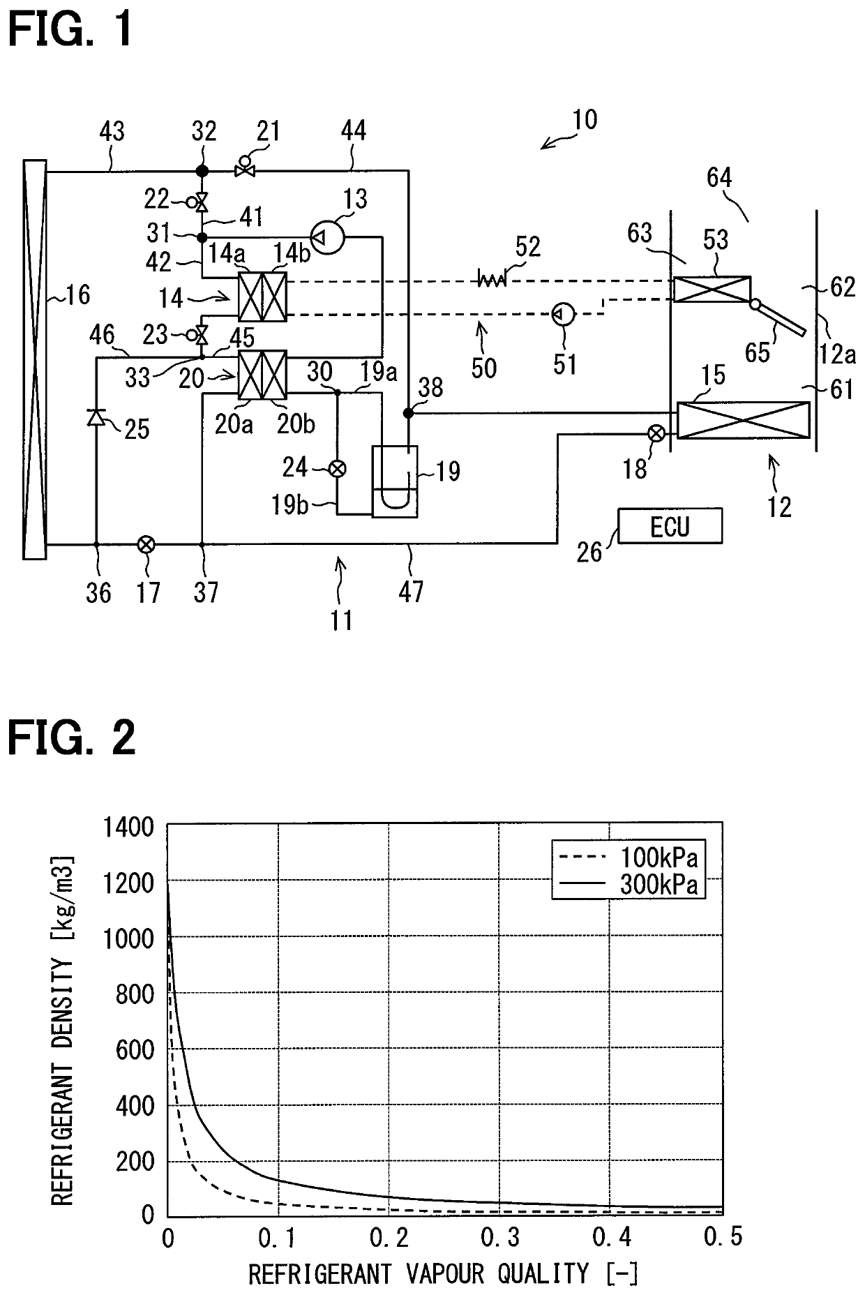
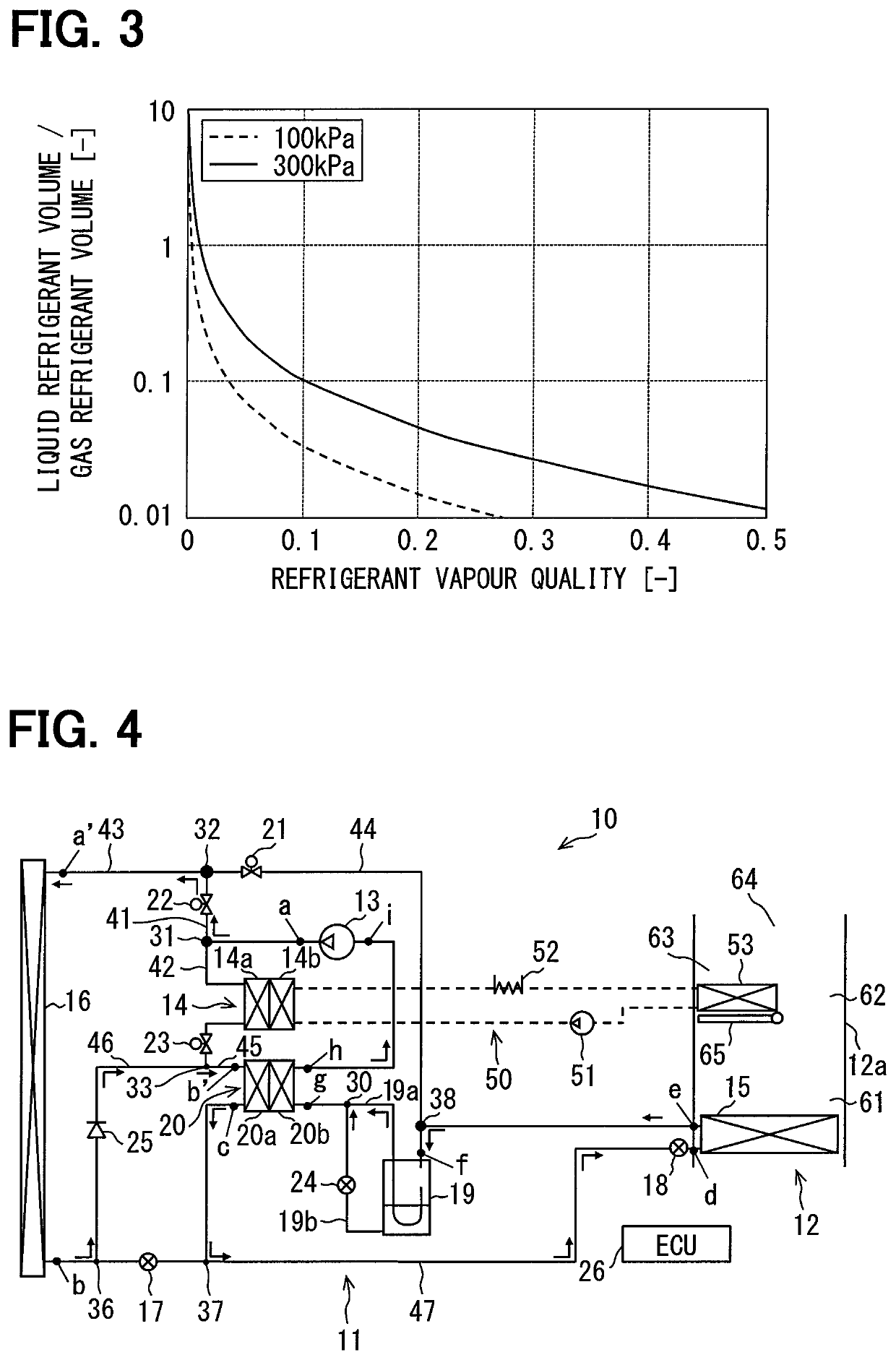
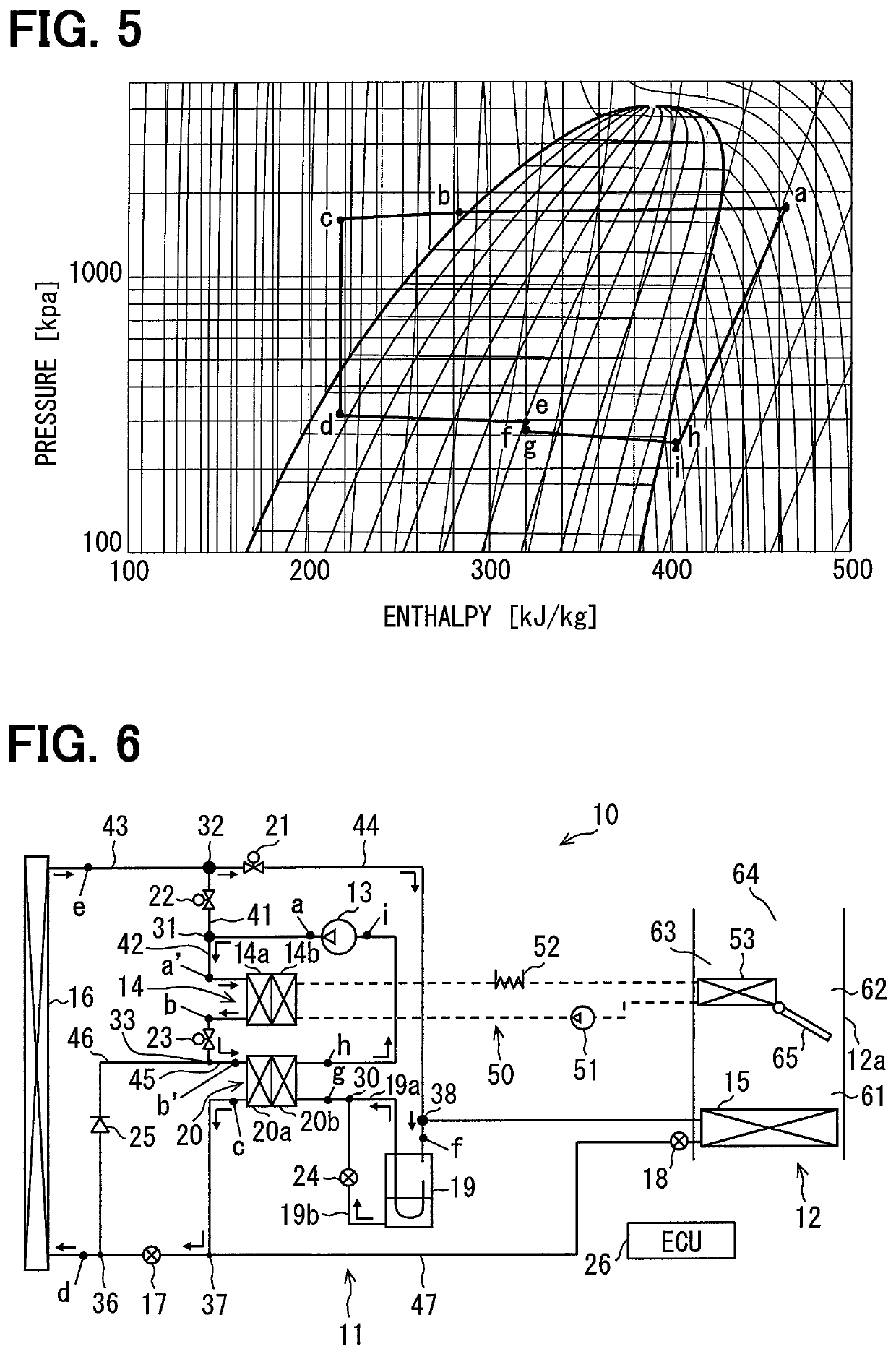
[0066]A first embodiment of the present disclosure will be described with reference to FIGS. 1 to 12. A heat pump system 10 of the present embodiment includes a heat pump cycle 11 and an air conditioning unit 12, and performs an air conditioning by using components illustrated in FIG. 1. The heat pump system 10 can be used in a vehicle such as a hybrid vehicle, an electric vehicle, and a fuel cell vehicle. The heat pump system 10 is configured to perform at least a heating operation and a cooling operation. The heat pump cycle 11 shown in FIG. 1 is an example of the heat pump cycle 11. In the heating operation, the refrigerant flow is a heating operation cycle described below. In the cooling operation, the refrigerant flow is a cooling operation cycle described below. In a dehumidifying operation, the refrigerant flow is a dehumidifying operation cycle described below.

[0067]First, the heat pump cycle 11 is described. The heat pump cycle 11 is constituted by refrigerant pipes through...

second embodiment

[0123]Next, a second embodiment will be described with reference to FIG. 13. In the present embodiment, it is characteristic that the amount of the liquid refrigerant flowing from the accumulator 19 to the internal heat exchanger 20 is controlled. In the heating pathway, the control unit 26 detects physical properties of the refrigerant drawn into the compressor 13 to estimate the vapour quality of the refrigerant, and the control unit 26 controls the flow rate regulator 24 such that the vapour quality becomes closer to a predetermined target value.

[0124]In order to maximize the efficiencies in both the cooling operation and the heating operation, it is required to control the superheat of the refrigerant drawn into the compressor 13. In the present embodiment, a thermosensitive portion 70 is provided between the low-pressure passage 20b of the internal heat exchanger 20 and the compressor 13.

[0125]The thermosensitive portion 70 detects the superheat based on the temperature and the...

third embodiment

[0129]Next, a third embodiment of the present disclosure is described below with reference to FIGS. 14 to 16. In the present embodiment, a connection position of the pipe located downstream of the accumulator 19 is different from the first embodiment, and the position of the thermosensitive portion 70 is different from the second embodiment.

[0130]The gas refrigerant passage 19a of the accumulator 19 is not connected to the upstream side of the low-pressure passage 20b of the internal heat exchanger 20, and the gas refrigerant passage 19a is connected to a second junction portion 30a that is located between the internal heat exchanger 20 and the compressor 13. Accordingly, the gas refrigerant flowing out of the accumulator 19 is directly drawn into the compressor 13. The liquid refrigerant passage 19b is connected to the low-pressure passage 20b of the internal heat exchanger 20. Accordingly, the liquid refrigerant flowing out of the accumulator 19 is drawn into the compressor 13 thr...


PUM


Abstract

A heat pump system includes a compressor that compresses and discharges a refrigerant, a decompressor that decompresses the refrigerant, an outdoor unit that exchanges heat between the refrigerant and an outside air, an evaporator that evaporates the refrigerant, a condenser that condenses the refrigerant, an internal heat exchanger, an accumulator that separates the refrigerant into a gas refrigerant and a liquid refrigerant, and a flow pathway changing portion. The internal heat exchanger includes a high-pressure passage through which a high-pressure refrigerant flows, and a low-pressure passage through which a low-pressure refrigerant flows, the internal heat exchanger exchanging heat between the refrigerant flowing through the high-pressure passage and the refrigerant flowing through the low-pressure passage. The flow pathway changing portion that switches between a cooling pathway and a heating pathway. According to this heat pump system, a cooling capacity and a heating capacity can be improved.

Description

CROSS REFERENCE TO RELATED APPLICATIONS[0001]This application is a U.S. National Phase Application under 35 U.S.C. 371 of International Application No. PCT / JP2016 / 070486 filed on Jul. 12, 2016 and published in Japanese as WO 2017 / 022421 A1 on Feb. 9, 2017. This application is based on and reference the benefit of priority from Japanese Patent Applications No. 2015-154332 filed on Aug. 4, 2015, and No. 2016-075387 filed on Apr. 4, 2016. The entire disclosures of all of the above applications are incorporated herein by reference.TECHNICAL FIELD[0002]The present disclosure relates to a heat pump system which circulates a refrigerant to heat and cool an air.BACKGROUND ART[0003]A common heat pump system is used in an air conditioner of a vehicle and includes a refrigeration cycle. A heat exchanger used in the refrigeration cycle functions as a condenser and an evaporator, for example, and exchanges heat between a refrigerant flowing in the heat exchanger and an air flowing outside the he...

Claims


Application Information

Patent Timeline
Patent Type & Authority Patents(United States)
IPC IPC(8): B60H1/00F25B43/00F25B25/00F25B6/02F25B41/20F25B1/10F25B39/04B60H1/22F25B13/00F25B40/00
CPCB60H1/22B60H1/00914B60H1/00921F25B1/10F25B6/02F25B13/00F25B25/005F25B39/04F25B40/00F25B41/20F25B43/006B60H2001/00928B60H2001/00957F25B2313/0233F25B2313/02741F25B2600/21F25B2600/2507F25B41/24
Inventor MIEDA, HIROSHISUGIMURA, RYOHEIKAWAKUBO, MASAAKIKAMI, YUICHI
Owner DENSO CORP
Why Eureka
Try Eureka