
Recharging electric generator system

Active Publication Date: 2021-12-07
GARDINER COTTRELL SALISBURY +1
View PDF9 Cites 0 Cited by
  • Summary
  • Abstract
  • Description
  • Claims
  • Application Information

AI Technical Summary

Benefits of technology

The patent describes a recharging electric generator system that overcomes limitations of previous systems. The system includes an inverting apparatus, a power source / storage device, a transformer unit, a rectifying unit, a switching device, and a power outlet / output terminal. The inverting apparatus makes and breaks electrical current, and the transformer unit steps up or down the voltage of the current. The rectifying unit converts alternating current to direct current, and the power source / storage device provides a sustainable source of energy for the system. The switching device controls the electrical connections between the various components and can start and stop the system. The system can also include one or more additional transformer units to transfer electrical energy to external sources. The system has a sensor / control unit to monitor the energy level and regulate the amount of energy transferred. The system can also include one or more additional features such as a primary transformer unit to adjust the voltage of the current, a series of additional transformer units, or a combination of these. Overall, the system provides a more efficient and flexible way to recharge electric generators.

Problems solved by technology

While these efforts have been noteworthy, there are still are some limitations, inefficiencies, and areas for improvement.
The use of electric and hybrid vehicles to some extent only diverts the problem of air pollution rather than resolving it.
In addition, some of the main reasons why electric cars have been disadvantaged in the past compared to internal combustion engine vehicles, include issues such as: limited autonomy, limited scope of application, and higher initial costs.
Efforts made in this area, e.g. to increase the autonomy of electric cars, do not however, sufficiently resolve these constraints in a cost-effective manner.
For example, the application of “eco-friendly” technologies comes at a higher cost, and as a result, the purchase price of electric cars tends to be more expensive than their fuel-based equivalents.
Hybrid vehicles are not sufficiently effective in addressing the issue of emissions, as fossil fuels continue to be used, although to a lesser extent.
The use of electric and battery driven vehicles are limited in their scope of application.
However, in metropolitan areas, where the air pollution is more problematic, the lack of sufficient charging stations is a considerable limiting factor, constrained for example, by the limited number of personal garages with electrical outlets, penury of parking spaces in general, limited number of charging stations, and the costs of installing new ones.
Inductive charging and wireless power transfer systems are also confined in their scope of application, as they are not conducive to conditions found in many developing countries which have less developed infrastructure such as paved roads, and which have limited or inconsistent supply of electricity.

Method used


Image

  • Recharging electric generator system
  • Recharging electric generator system
  • Recharging electric generator system

Examples


Embodiment Construction

[0026]Embodiments of the present invention will be described in detail hereinafter with reference to the drawings, in which the same or corresponding portions are denoted with the same reference characters and a description thereof may not be repeated.

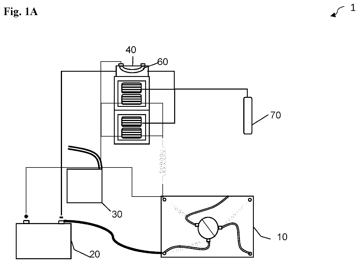
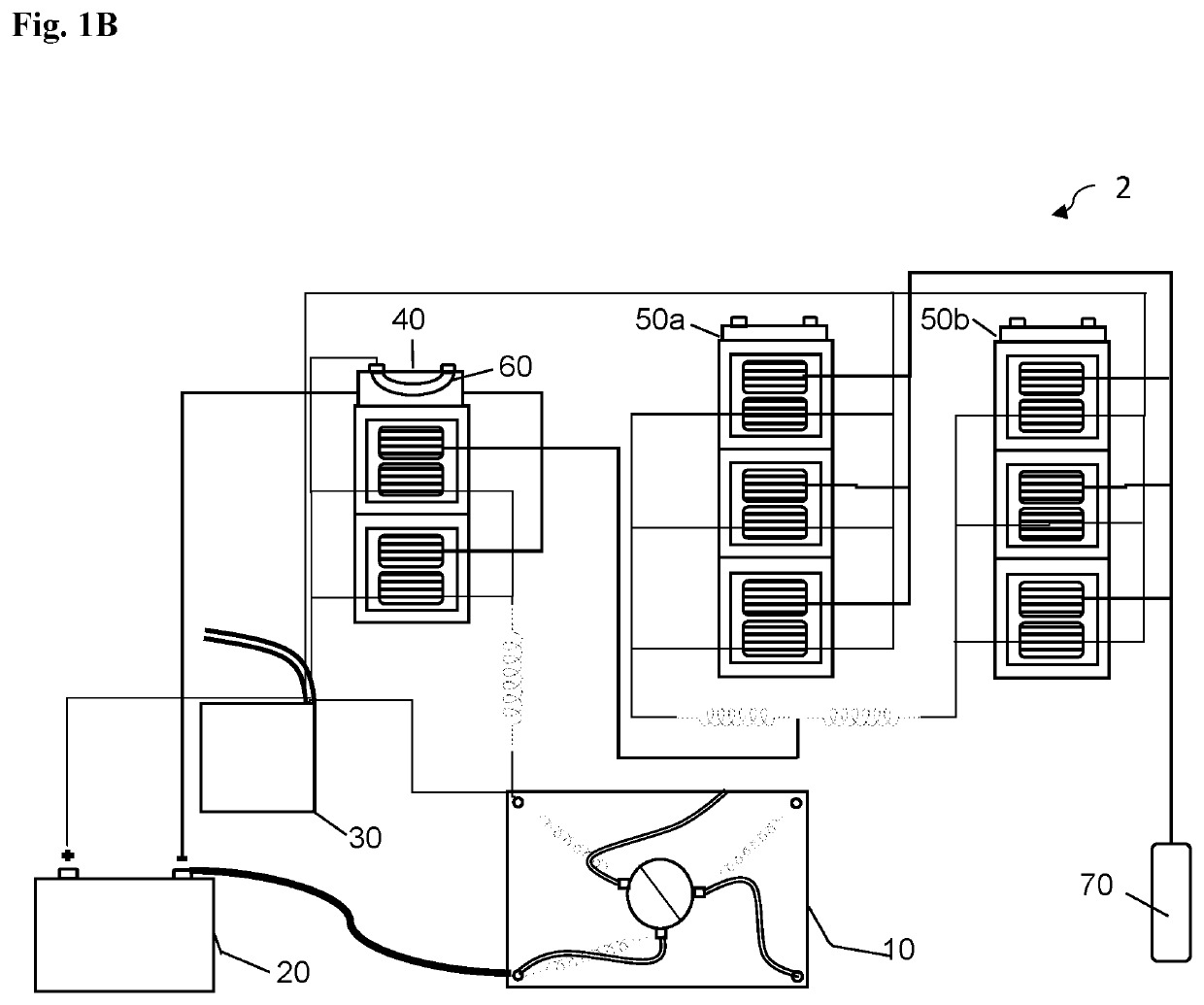
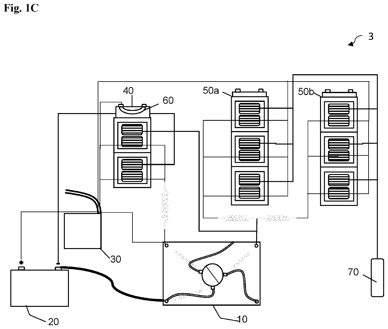
[0027]FIG. 1A is an overall configuration diagram of a recharging electric generator system according to a first configuration of the invention. Referring to FIG. 1A, a recharging electric generator system 1 comprises at least one inverting apparatus 10 or 10B, at least one power source / storage device 20, a switching device 30, at least one transformer unit 40, and at least one rectifying unit 60 and at least one power outlet / output terminal 70.

[0028]In a first configuration of the subject matter, a recharging electric generator system comprises at least one inverting apparatus 10 configured to make and break electrical current. At least one power source / storage device 20 is connected to the at least one inverting apparatus 10. The at ...


PUM


Abstract

A recharging electric generator system which generates electrical energy and recharges itself, and methods thereof. A recharging electric generator system comprises at least one inverting apparatus; at least one power source / storage device to start the system and store electrical energy; at least one switching device; at least one transformer unit to adjust the voltage of the electrical energy, at least one rectifying unit to convert a portion of the electrical energy from alternating current to direct current and to transfer electrical energy to recharge the at least one power source / storage device; and at least one power outlet / output terminal to distribute electrical energy for further use. A recharging electric generator system seeks to provide of renewable source of energy which could be applied to different sectors and is conducive to conditions in both developed and developing countries.

Description

BACKGROUND OF THE INVENTION1. Field[0001]This specification relates to a system which generates electrical energy and recharges itself, and methods thereof.2. Description of the Related Art[0002]Given the increased awareness of the negative effects that fossil fuel emissions can have on the environment and on respiratory health, considerable efforts have been made to reduce emissions, by for example, enhancing the efficiency of combustion engine vehicles, or by increasing the use of electric or hybrid vehicles. Beyond of the automobile industry, efforts have also been made to use cleaner, more ecologically friendly sources of energy, such as solar, wind, hydrology, clean coal, etc.[0003]While these efforts have been noteworthy, there are still are some limitations, inefficiencies, and areas for improvement. The use of electric and hybrid vehicles to some extent only diverts the problem of air pollution rather than resolving it. This is because the increased use of electric and hybri...

Claims


Application Information

Patent Timeline
IPC IPC(8): H02K25/00H02K27/00H02K53/00H02J7/00H02M7/04H02J9/06
CPCH02K53/00H02J7/0042H02J9/061H02J9/068H02M7/043H02M7/04H02M7/44H02J7/1492H02J2310/48Y02T10/92
Inventor GARDINER, COTTRELL SALISBURYGARDINER, SAMANTHA RENE
Owner GARDINER COTTRELL SALISBURY
Learn More