Construction toy with interconnecting strips and rings

a construction toy and interconnection technology, applied in the field of construction toys, can solve the problems of complex interplay between these criteria, relates to the choices available, and related limitations arise from the fixed length of the strut elements, and achieves the effect of relative eas

Active Publication Date: 2021-12-21
KAYE GEORGE FENWICK
View PDF33 Cites 2 Cited by
  • Summary
  • Abstract
  • Description
  • Claims
  • Application Information

AI Technical Summary

Benefits of technology

[0011]In addressing the above listed and other limitations, the invention gives users opportunities to create diverse, compelling forms of their own design with relative ease. The invention as a whole challenges the user with a unique system of conventions for constructing forms, and within this system a limitless field of possibilities.
[0014]The strips are long, rectilinear elements. In one embodiment, the strips have a width that is proportionate to their thickness such that for a given circle with radius r two strips stacked flat end-to-end present a rectangular profile at the end that may be inscribed within the circle (FIG. 1C). In one embodiment, the strips are half as thick as they are wide, such that two strips stacked flat end-to-end present a square profile at the end. The strips can flex into a curve that can be held in tension. The strips may also be worked into shallow curves that retain their shape without tension. The strips may be of a single standard length that optimizes functionality and safety. The strips may be scored at regular intervals on one of the wide faces such that a strip can be easily broken at a score, and thus edited to shorter lengths (FIGS. 4 & 5). When flexed into a curve with the scores facing outwards (e.g. away from the radius of the curve), a strip will break easily. The breaking point can be controlled by the fingers, or by passing the strip through a hole in a ring and using the ring as leverage (useful especially for breaking off end segments). When flexed with the scored side facing inwards (e.g. towards the radius of the curve) the strip stays intact. The strips may also feature a small “v” fork on both ends and an incision at the base of the fork allowing for two sides of the fork to come apart at the ends. In this way, a string or thin slip may be wedged tightly in between the two sides of the fork at the end of a strip. A string thus attached may function as a connector to another strip similarly attached, or to an anchor from which a form is suspended (FIG. 6). A thin slip may serve as a wedge that prevents the strip from sliding through holes in a connector element.
[0016]The rings are cylindrical with a hollow center, of several standard diameters. A plurality of holes on the sides of each ring are aligned such that a strip can pass through two holes, crossing inside (e.g. cross-cutting the cylinder). In one embodiment, the holes are sized to circumscribe two strips stacked flat against one another. In this configuration, the strips fit tightly into the holes and together provide greater structural strength than that of a single strip (FIG. 8). A single strip will slide freely through the holes. In this configuration, the ring will spin freely around the strip when the strip is held secure.
[0030]In combination, these features allow for a great range of joining possibilities and possible resulting forms.

Problems solved by technology

The interplay between these criteria is complex, with evident trade-offs.
One such limitation relates to the choices available at a given joint for the articulation of the parts.
A second related limitation arises from the fixed length of the strut elements.
A third limitation relates to tradeoffs between structural strength and flexibility of the struts.
The thinner a strut the more easily it may bend and / or twist, but the more breakable it may become.
Thick, rigid struts on the other hand may provide structural strength but limit the possible achievable forms (i.e. limit the toy's versatility).
Tube-shaped struts have the disadvantage that they cannot present flat against one another or against other attachments however, limiting their aesthetic appeal in certain applications as well as their usability.

Method used


Image

  • Construction toy with interconnecting strips and rings
  • Construction toy with interconnecting strips and rings
  • Construction toy with interconnecting strips and rings

Examples


Embodiment Construction

[0110]The construction toy of the invention includes numerous components that may be assembled in various ways to achieve desired combinations, as discussed below. The construction toy of the invention is designated generally 10. Example assemblies constructed of the components of construction toy 10 may be seen in FIGS. 33-48.

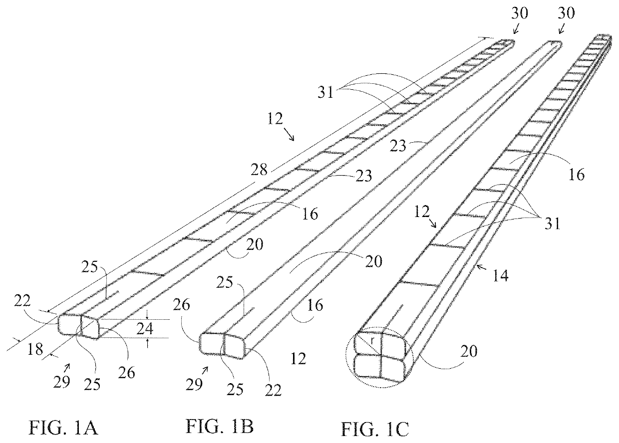
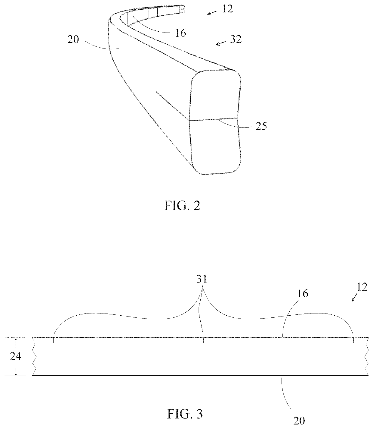
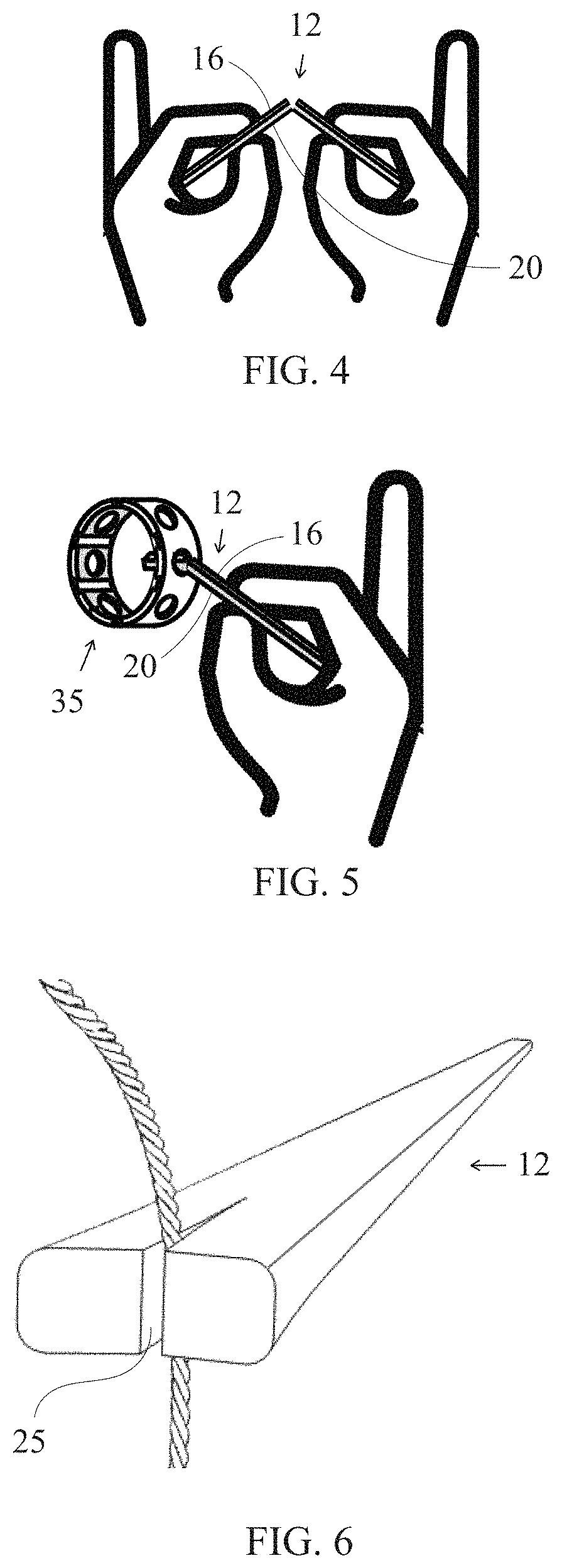
[0111]Referring now to FIGS. 1A through 1C, construction toy 10 includes a plurality of strips, including first strip 12 and second strip 14. Each of strips 12 and 14 have a top surface 16 having width 18, and a bottom surface 20 having width 18. First edge 22 has thickness 24. Second edge 26 also has thickness 24. First strip 12 and second strip 14 have a length 28, four longitudinal edges 23 a first end 29 and a second end 30. In one embodiment, first end 29 and second end 30 are forked and an incision 25 bisecting each end extends from the vertex of the fork a distance, e.g., 1% to 5% or 4% to 2% or approximately 3%, down the length of the strip. Top surfac...


PUM


Abstract

The invention is a construction toy consisting of standard connector elements, e.g., rings, and strut elements, e.g., that may be joined in various angular configurations and with various types of articulation such as fixed, sliding, swinging, spinning, etc. Rings may be provided that have pairs of perimeter orifices that are offset by different amounts wherein the different offsets provide different functionality to ring and strut assembles. Other elements may be included such as pipes, slips, caps, base components and collar components. The elements may be combined to create various forms including a figure with human traits comprised of interconnecting strips and rings of various dimensions, a decoration, a vehicle, a bird, or many other forms in accordance with a user's imagination.

Description

CROSS REFERENCE TO RELATED APPLICATIONS[0001]This application claims the priority of U.S. Provisional Patent Application No. 62 / 769,910 titled “CONSTRUCTION TOY WITH INTERCONNECTING STRIPS AND RINGS,” filed Nov. 20, 2018, the contents of which are hereby incorporated by reference.FIELD OF THE INVENTION[0002]The invention relates to toys. More particularly, the invention is a construction toy consisting of various pieces that may be assembled and disassembled to create many different imaginative forms. The invention addresses the problem of satisfying the complex criteria for a useful construction toy through a new system of connecting parts.BACKGROUND OF THE INVENTION[0003]Construction toys offer users a framework for exploring materials, expressing creative ideas and developing many important skills. Construction toys share in common the requirement that individual pieces may be joined together to build composite forms. The invention may be considered among a category of “strut and...

Claims


Application Information

Patent Timeline
Patent Type & Authority Patents(United States)
IPC IPC(8): A63H33/10
CPCA63H33/102A63H33/108A63H33/12
Inventor KAYE, GEORGE FENWICK
Owner KAYE GEORGE FENWICK
Why Eureka
Try Eureka