Diffractive null corrector employing a spatial light modulator

a spatial light modulator and null corrector technology, applied in the field of lithography, can solve the problems of high manufacturing cost, limited accuracy and the types of aspheric surfaces that can be tested by null correctors, and the non-recurring cost associated with null correctors adds significantly to the cost and delivery schedule of optical elements that are analyzed by null correctors, so as to reduce the cost of fabrication

Inactive Publication Date: 2008-04-03
ASML HLDG NV
View PDF43 Cites 8 Cited by
  • Summary
  • Abstract
  • Description
  • Claims
  • Application Information

AI Technical Summary

Benefits of technology

[0009]Embodiments of the present invention meet the above-identified needs by providing a diffractive null corrector employing a spatial light modulator (SLM) to generate aspheric wavefronts. Such a diffractive null corrector allows for a reduction in the cost of fabrication because a diffractive null corrector using an SLM may be used to analyze aspherical optical surfaces of almost any profile. Furthermore, because the actuation state of pixels of the SLM may be varied, a diffractive null corrector employing SLMs may compensate for unexpected errors or problems occurring in the optics of the diffractive null corrector.
[0012]In a further feature, any residual position errors associated with the actuation state of the SLM pixels can be calibrated. In this example, the SLM pixels are set to generate a spherical wavefront, instead of using the SLM to create an aspheric wavefront. An advantage of a spherical wavefront is the relative ease with which an absolute calibration on that wavefront may be performed. Based on this calibration, data may be incorporated into a module that generates a grating pattern used in a null test. A null test that utilizes such a calibration technique will have greater accuracy compared to a null test that does not include any such calibration technique.
[0013]A diffractive null corrector employing an SLM in accordance with an embodiment of the present invention has several example advantages over conventional null correctors. For example, diffractive null correctors employing SLMs may reduce the costs and schedule delays associated with building null correctors because such a diffractive null corrector may be used to analyze optical surfaces of various shapes.
[0015]As a still further example, a diffractive null corrector employing an SLM may compensate for low fringe contrast by using a gray scaling capability of the SLM. In a typical null corrector, low fringe contrast may compromise the accuracy of an interferometric measurement. A difference in the amplitude of the test and reference beams in the interferometer can cause a reduction in fringe contrast. The amplitude of electromagnetic radiation emerging from an SLM may be adjusted using a technique called “gray scaling.” Using such a gray scaling technique, the amplitude of the test beam may be adjusted to match the reference beam, and thereby ensuring maximum fringe contrast during a null test.

Problems solved by technology

Null correctors that include refractive and / or reflective optical elements have limitations with respect to accuracy and the types of aspheric surfaces that can be tested.
A problem with null correctors is that they are expensive to fabricate.
The non-recurring cost associated with a null corrector significantly adds to the cost and delivery schedule of an optical element that is analyzed by a null corrector.
Because aspherical optical surfaces are typically analyzed using a null corrector, typical asphere-based optical designs cost more and take longer to fabricate than all-sphere optical designs.
Thus, although an asphere-based optical design typically has superior optical quality compared to an all-sphere optical design, cost and schedule usually drive customers to select all-sphere optical designs.
However, this technique only works over a limited range of asphericity because aberrations due to the asphericity can cause rays propagating through the interferometer system to be vignetted, and thereby prevent the whole optical surface from being analyzed.

Method used


Image

  • Diffractive null corrector employing a spatial light modulator
  • Diffractive null corrector employing a spatial light modulator
  • Diffractive null corrector employing a spatial light modulator

Examples


Embodiment Construction

I. Introduction

[0030]A. Overview

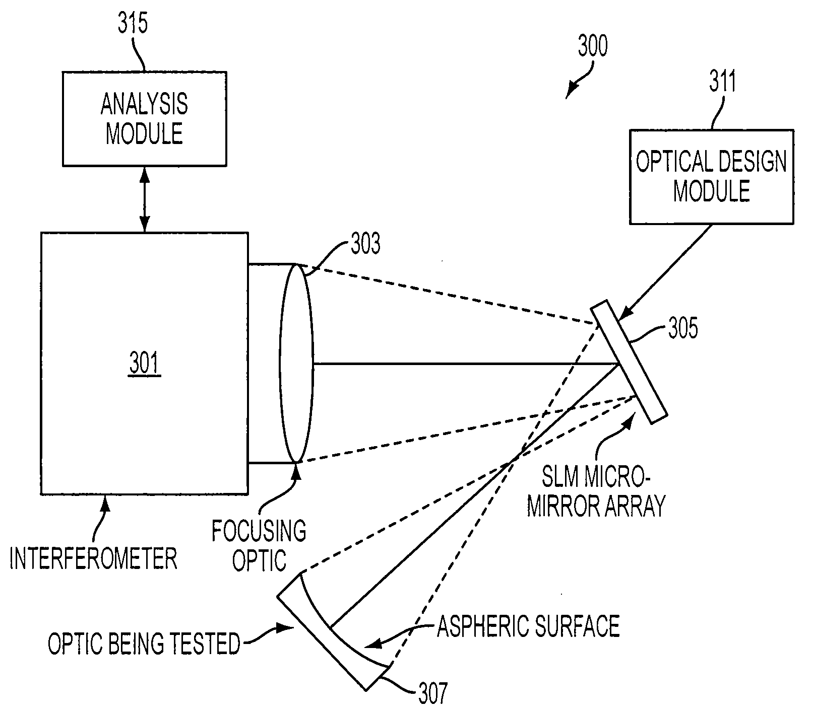
[0031]Embodiments of the present invention are directed to a diffractive null corrector employing an SLM and a method for using such a diffractive null corrector. An example diffractive null corrector in accordance with an embodiment of the present invention is used to test an aspheric optical surface. In this embodiment, an interferometer provides a test beam of electromagnetic radiation to the SLM. The test beam is focused to have an f-number that is nominally optically conjugate to the aspheric optical surface being tested. In an embodiment, the test beam may be focused by the SLM. The test beam is first incident on the SLM. Pixels of the SLM are selectively turned ON / OFF to provide a grating pattern that generates a wavefront shape resulting in a null test of the aspheric optical surface.

[0032]A null corrector changes the direction of rays that make up an input beam so each ray hits an optical surface at normal incidence. If the optical surface is...


PUM


Abstract

The present invention is directed to a system and method for using a spatial light modulator (SLM) to perform a null test of an (aspheric) optical surface. In an embodiment, such a system includes an interferometer, an optical element, and an SLM. The interferometer provides electromagnetic radiation. The optical element conditions the electromagnetic radiation to provide a first beam of radiation and a second beam of radiation. The SLM shapes a wavefront of the first beam of radiation resulting in a shaped wavefront corresponding to an optical surface. The shaped wavefront is incident on and conditioned by the optical surface. The shape of the optical surface is analyzed based on a fringe pattern resulting from interference between the shaped wavefront mapped by the optical surface and the second beam of radiation. The system may also include an optical design module that converts a null corrector design corresponding to the optical surface into instructions for the SLM.

Description

BACKGROUND OF THE INVENTION[0001]1. Field of the Invention[0002]The present invention is generally directed to lithography, and more particularly to testing lithographic apparatuses.[0003]2. Background Art[0004]A null corrector is a device that may be used to analyze an optical surface, such as a spherical optical surface or an aspherical optical surface. A typical null corrector includes an interferometer, reference optics (such as one or more mirrors and / or one or more lens), and a test optical surface. The interferometer provides a test beam and a reference beam. The test beam is conditioned by the reference optics and then incident on the test optical surface. If the test optical surface is “ideal” (i.e., fabricated within predetermined specifications), the beam conditioned by the reference optics impinges on the test optical surface at (approximately) normal incidence. A wavefront that impinges on a test optical surface at (approximately) normal incidence is referred to herein ...

Claims


Application Information

Patent Timeline
Patent Type & Authority Applications(United States)
IPC IPC(8): G01B11/02
CPCG01B11/2441G01J2009/0223G01M11/0271G01M11/025G01M11/0264G01M11/005
Inventor HARNED, NORA-JEANHARNED, ROBERT D.
Owner ASML HLDG NV
Why Eureka
Try Eureka