Systems for a radio frequency coil for mr imaging

a radio frequency coil and imaging technology, applied in the field of magnetic resonance imaging (mri), can solve the problems of unsatisfactory positioning, sized and/or positioned non-ideally, bulky conventional rf coils, etc., and achieve the effect of reducing the cost and weight of conventional rf coils, reducing the relative ease of use, and minimizing materials

Active Publication Date: 2019-10-10
GENERAL ELECTRIC CO
View PDF0 Cites 11 Cited by
  • Summary
  • Abstract
  • Description
  • Claims
  • Application Information

AI Technical Summary

Benefits of technology

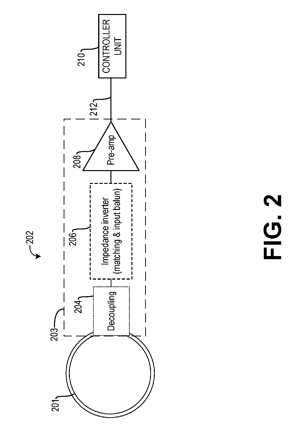
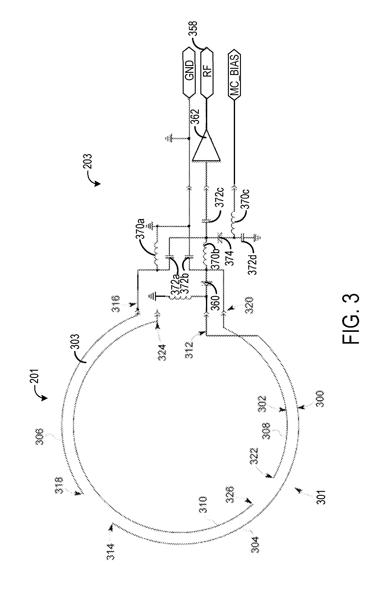
[0005]In one embodiment, a radio frequency (RF) coil assembly for a magnetic resonance (MRI) system includes a loop portion comprising distributed capacitance wires, a coupling electronics portion including a pre-amplifier, and a disposable material enclosing at least the loop portion, the disposable material comprising one or more of paper, plastic, and / or cloth. In this way, a flexible and disposable RF coil assembly may be provided that allows for RF coils in an array to be positioned more arbitrarily, allowing placement and / or size of the coils to be based on desired anatomy coverage, without having to account for fixed coil overlaps or electronics positioning. The coils may adapt and conform to the patient anatomy or semi-rigid housing contours with relative ease. Additionally, the cost and weight of the RF coils may be significantly lowered due to minimized materials and production process, and environmentally-friendlier processes may be used in the manufacture and miniaturization of the RF coils of the present disclosure versus conventional RF coils. Accordingly, due to the low-cost and low amount of materials, the RF coils may be disposable, enabling customized arrangements of the RF coils and decreasing operator maintenance of the RF coils.

Problems solved by technology

However, conventional RF coils tend to be bulky, rigid and are configured to be maintained at a fixed position relative to other RF coils in an array.
This bulkiness and lack of flexibility often prevents the RF coil loops from coupling most efficiently with the desired anatomy and make them very uncomfortable to the imaging subject.
Further, coil-to-coil interactions dictate that the coils be sized and / or positioned non-ideally from a coverage or imaging acceleration perspective.

Method used


Image

  • Systems for a radio frequency coil for mr imaging
  • Systems for a radio frequency coil for mr imaging
  • Systems for a radio frequency coil for mr imaging

Examples


Embodiment Construction

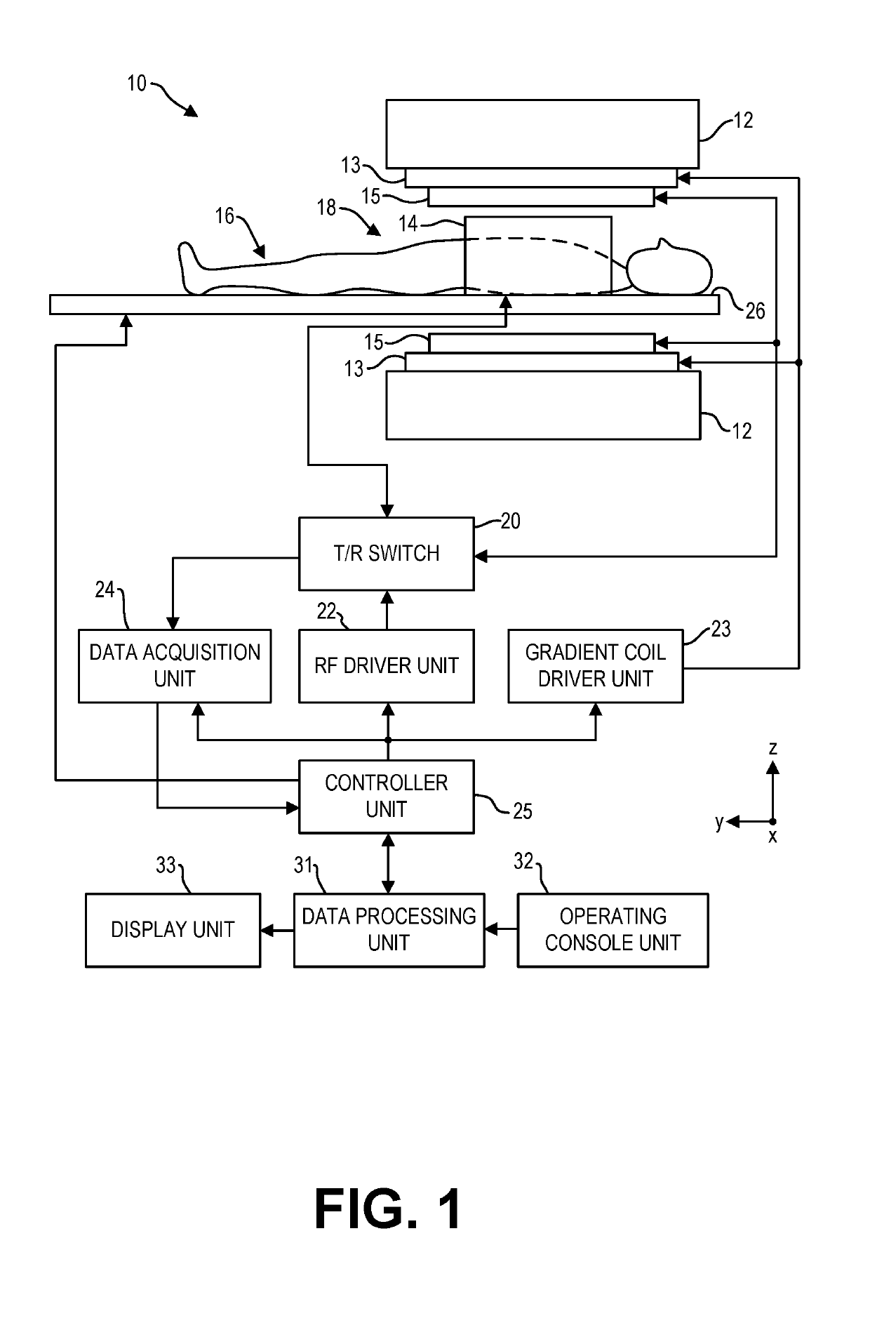
[0022]The following description relates to various embodiments of a radio frequency (RF) coil in MRI systems. In particular, systems and methods are provided for a low-cost, flexible, and lightweight RF coil that is effectively transparent in multiple respects. The RF coil is effectively transparent to patients, given the low weight of the coil and flexible packaging that is enabled by the RF coil. The RF coil is also effectively transparent to other RF coils in an array of RF coils, due to minimization of magnetic and electric coupling mechanisms. Further, the RF coil is effectively transparent to other structures through capacitance minimization and is transparent to positrons through mass reduction, enabling use of the RF coil in hybrid positron emission tomography (PET) / MR imaging systems. The RF coil may be of such low-cost that the RF coil may be disposable. The RF coil of the present disclosure may be used in MRI systems of various magnetic field strengths.

[0023]The RF coil o...


PUM


Abstract

Various methods and systems are provided for a flexible, lightweight, and low-cost disposable radio frequency (RF) coil of a magnetic resonance imaging (MRI) system. In one example, an RF coil assembly for an MRI imaging system includes a loop portion comprising distributed capacitance conductor wires, a coupling electronics portion including a pre-amplifier; and a disposable material enclosing at least the loop portion, the disposable material comprising one or more of paper, plastic, and/or cloth.

Description

CROSS REFERENCE TO RELATED APPLICATIONS[0001]The present application claims priority to U.S. Provisional Patent Application No. 62 / 425,991, entitled “SYSTEMS FOR A RADIO FREQUENCY COIL FOR MR IMAGING,” filed Nov. 23, 2016, the entire contents of which are hereby incorporated by reference for all purposes.FIELD[0002]Embodiments of the subject matter disclosed herein relate to magnetic resonance imaging (MRI), and more particularly, to MRI radio frequency (RF) coils.BACKGROUND[0003]Magnetic resonance imaging (MRI) is a medical imaging modality that can create images of the inside of a human body without using x-rays or other ionizing radiation. MRI systems include a superconducting magnet to create a strong, uniform, static magnetic field. When a human body, or part of a human body, is placed in the magnetic field, the nuclear spins associated with the hydrogen nuclei in tissue water become polarized, wherein the magnetic moments associated with these spins become preferentially align...

Claims


Application Information

Patent Timeline
Patent Type & Authority Applications(United States)
IPC IPC(8): G01R33/34G01R33/3415G01R33/36
CPCG01R33/3621G01R33/3415G01R33/34007G01R33/481G01R33/3685A61B5/055G01R33/00
Inventor STORMONT, ROBERT STEVENLINDSAY, SCOTT ALLENCHU, DASHENMATIAS, RICARDO M.
Owner GENERAL ELECTRIC CO
Why Eureka
Try Eureka