Powdery-material feeding device and powdery-material feeding method

a technology of powdery materials and feeding devices, which is applied in the direction of packaging goods, manufacturing tools, instruments, etc., can solve the problems of difficult to find a molded product containing such a biologically-originated foreign matter by checking completed molded products

Active Publication Date: 2021-12-28
KIKUSUI SEISAKUSHO LTD
View PDF30 Cites 2 Cited by
  • Summary
  • Abstract
  • Description
  • Claims
  • Application Information

AI Technical Summary

Benefits of technology

[0004]It is an exemplary object of the present invention to prevent the compression-molding machine from producing a molded product that mixedly contains a biologically-originated foreign matter.
[0005]The invention exemplarily provides a powdery-material feeding device configured to feed a powdery material to a compression-molding machine configured to obtain a molded product by filling a die bore with the powdery material and to compress the powdery material with punches. The powdery-material feeding device includes a detector configured to detect a biologically-originated foreign matter mixedly contained in the powdery material to be fed to the compression-molding machine, and a controller configured to control to remove the powdery material mixedly containing the biologically-originated foreign matter detected by the detector to avoid feeding of the powdery material mixedly containing the foreign matter to the compression-molding machine, or to control to stop the feeding of the powdery material to the compression-molding machine. This configuration prevents feeding, to the molding machine, of the powdery material mixedly containing the biologically-originated foreign matter.
[0006]The powdery-material feeding device is further configured to feed the compression-molding machine with mixed powdery materials containing at least two types of powdery materials. The powdery-material feeding device includes a detector configured to measure a mixing degree of the mixed powdery materials to be fed to the compression-molding machine. When the mixing degree of the mixed powdery materials detected by the detector is out of a predetermined range, the controller controls to remove the mixed powdery materials to avoid the feeding to the compression-molding machine or controls to stop the feeding of the mixed powdery materials to the compression-molding machine. This configuration prevents the feeding, to the molding machine, of the mixed powdery materials having a mixing degree out of a normal range as well as a biologically-originated foreign matter, to keep high quality of molded products.
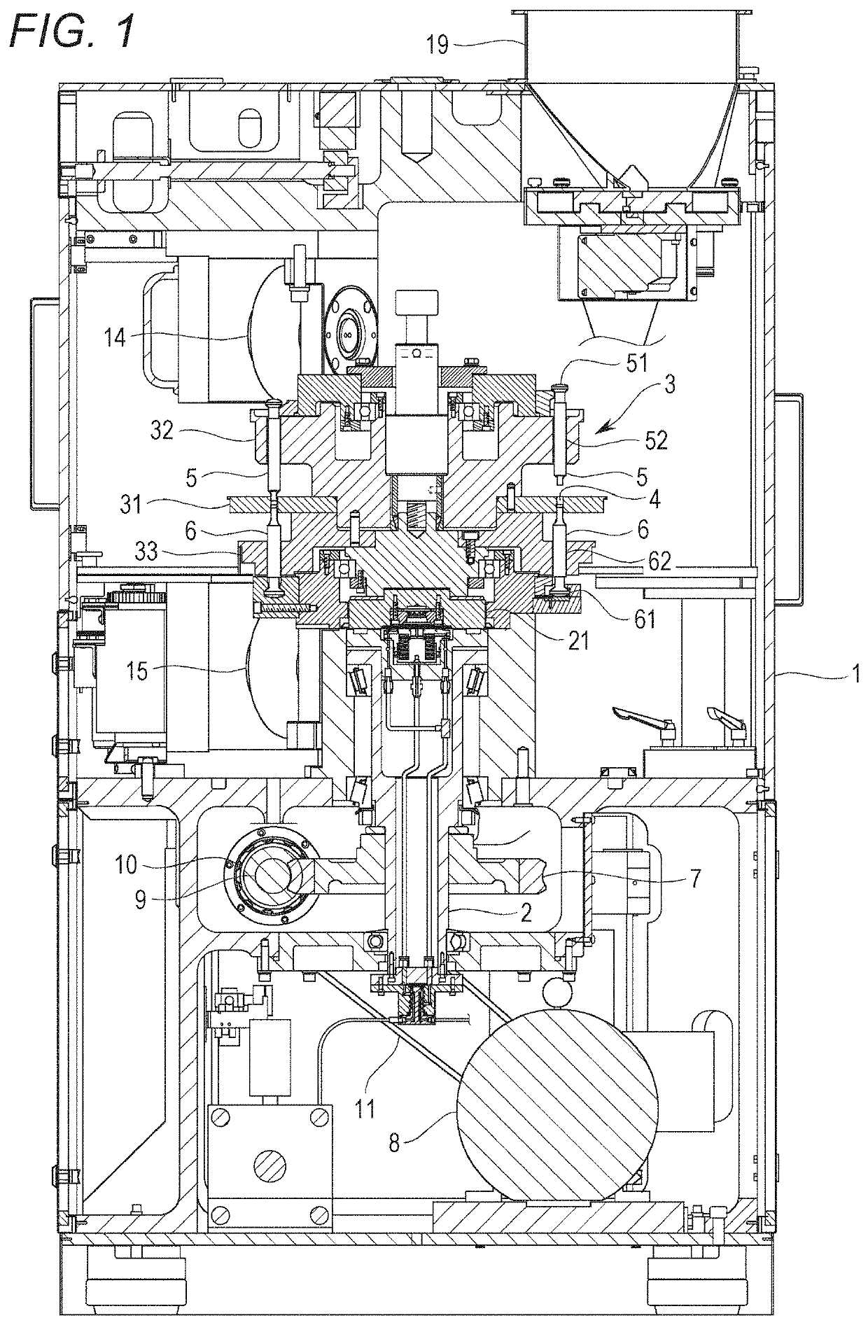
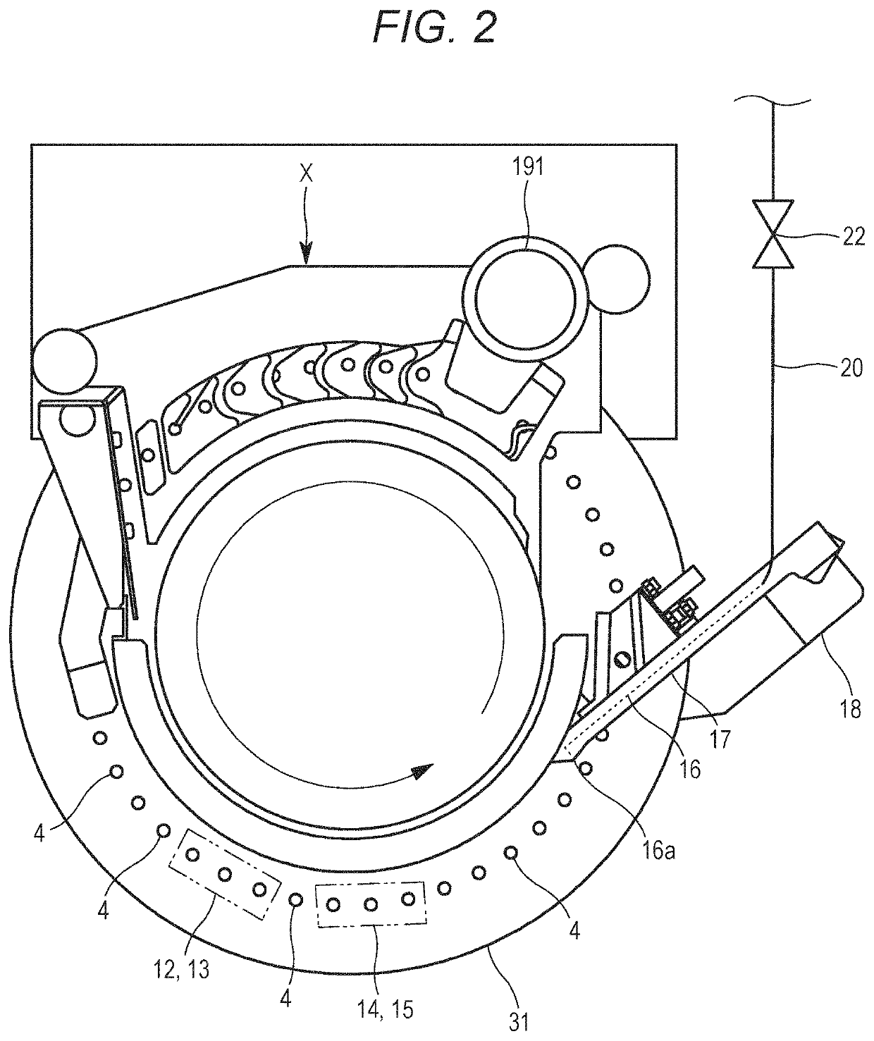
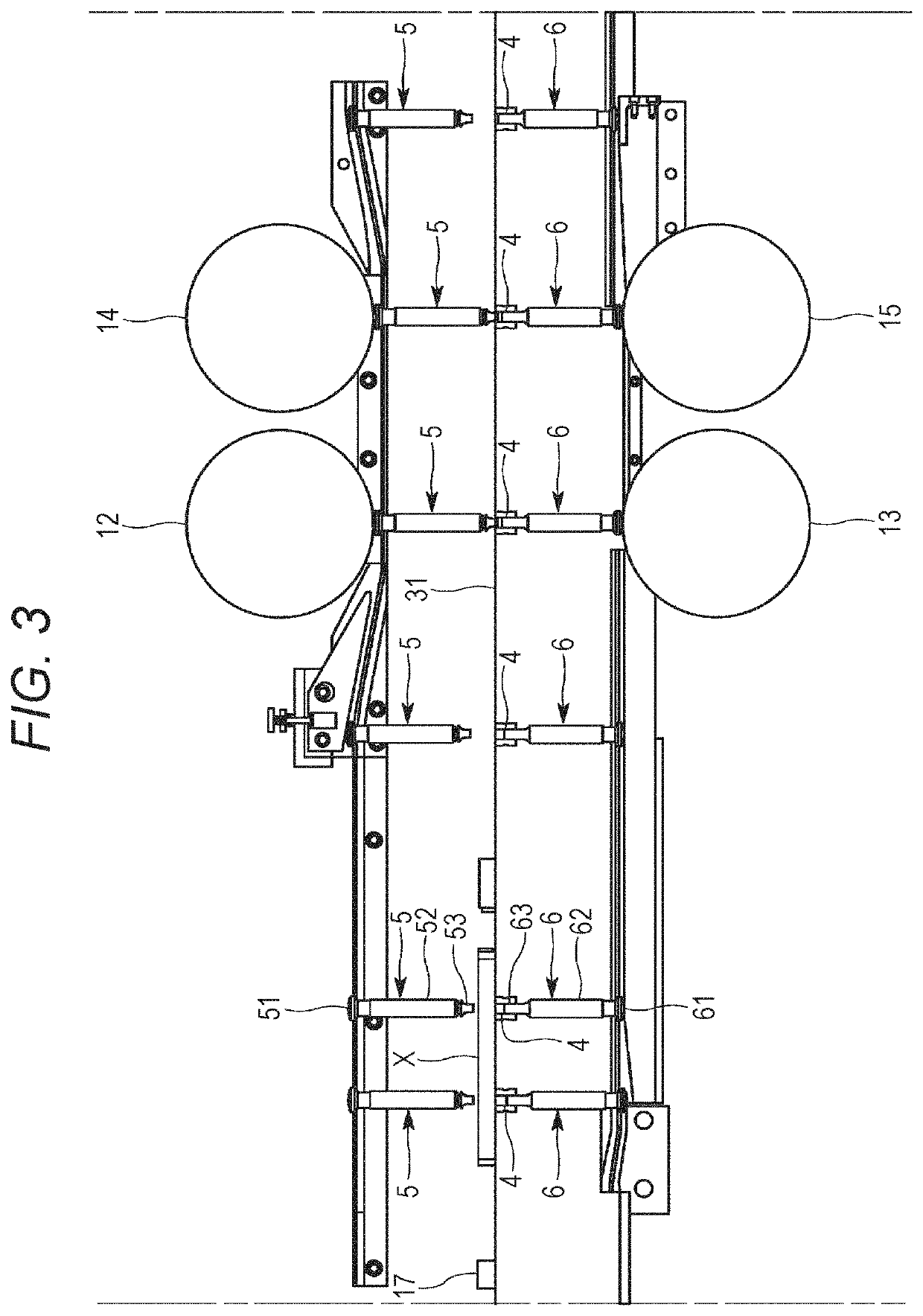
[0007]When the powdery-material feeding device removes a powdery material mixedly containing foreign matter or powdery materials having an abnormal mixing degree, the powdery material fed from the powdery-material feeding device to the compression-molding machine can have a temporarily decreased flow rate per unit time. The compression-molding machine includes a rotary compression-molding machine and is configured to rotate a turret including a table having a die bore, and punch retaining portions vertically slidably retaining punches disposed above and below the die bore, along with the punches, and fill the die bore with a powdery material from a filling device disposed just above the table, to compress the powdery material filled in the die bore with the punches and to obtain a molded product. The controller controls to adjust a rotational speed of the turret and the punches of the rotary compression-molding machine to allow the powdery material in a feed pipe directly connected to the filling device and is further configured to feed the powdery material toward the filling device or in the filling device to have an upper surface level kept within a constant target range. This configuration achieves adjustment of an amount per unit time of a powdery material used by the molding machine in accordance with the flow rate of the powdery material fed from the powdery-material feeding device to the filling device.
[0008]Specifically, an increase in a rotational speed of the turret and the punches leads to an increase in an amount of the used powdery material per unit time, whereas a decrease in a rotational speed of the turret and the punches leads to a decrease in an amount of the used powdery material per unit time. An increase in an amount of the used powdery material per unit time leads to a decrease in an upper surface level of the powdery material in the feed pipe directly connected to the filling device or in the filling device, whereas a decrease in an amount of the used powdery material per unit time leads to an increase in an upper surface level of the powdery material in the feed pipe or in the filling device. When the upper surface level of the powdery material in the feed pipe or in the filling device is kept within a constant target range by adjustment of the rotational speed of the turret and the punches of the rotary compression-molding machine, the powdery material in the filling device constantly keeps pressure, and the filling device can keep filling the die bores with a constant amount of the powdery material. This leads to suppression of variation in weight, size, tableting pressure, and the like of the produced molded products.
[0013]The exemplary invention may prevent the compression-molding machine from producing a molded product that mixedly contains a biologically-originated foreign matter.

Problems solved by technology

In another case where the powdery material fed to the compression-molding machine mixedly contains a biologically-originated foreign matter like a human hair or a bug, and molded products are produced from the powdery material, it is difficult to find a molded product containing such a biologically-originated foreign matter by checking completed molded products.

Method used


Image

  • Powdery-material feeding device and powdery-material feeding method
  • Powdery-material feeding device and powdery-material feeding method
  • Powdery-material feeding device and powdery-material feeding method

Examples


Embodiment Construction

[0035]An exemplary embodiment of the exemplary invention will now be described with reference to the drawings. Initially described is an overview of an entire rotary compression-molding machine (hereinafter, referred to as the “molding machine”) according to the exemplary embodiment. As shown exemplarily in FIG. 1, the molding machine includes a frame 1 accommodating an upright shaft 2 that functions as a rotary shaft, and a turret 3 that is attached to a connection portion 21 disposed at the top of the upright shaft 2. A worm wheel 7 is attached to the lower end of the upright shaft 2. The worm wheel 7 meshes with a worm gear 10. The worm gear 10 is fixed to a gear shaft 9 that is driven by a motor 8. Drive power outputted from the motor 8 is transmitted to the gear shaft 9 by way of a belt 11, so as to rotate the upright shaft 2 by way of the worm gear 10 and the worm wheel 7. Rotation of the upright shaft 2 causes rotation of the turret 3 and punches 5 and 6.

[0036]The turret 3 ho...


PUM

PropertyMeasurementUnit
speedaaaaaaaaaa
mixing degreeaaaaaaaaaa
rotational speedaaaaaaaaaa

Abstract

A powdery-material feeding device is configured to feed a powdery material to a compression-molding machine configured to obtain a molded product by filling a die bore with the powdery material and to compress the powdery material with punches. The powdery-material feeding device includes a detector configured to detect a biologically-originated foreign matter mixedly contained in the powdery material to be fed to the compression-molding machine, and a controller configured to control to remove the powdery material mixedly containing the biologically-originated foreign matter detected by the detector to avoid feeding of the powdery material mixedly containing the biologically-originated foreign matter to the compression-molding machine, or to control to stop the feeding of the powdery material to the compression-molding machine.

Description

BACKGROUND[0001]There has been known a rotary compression-molding machine including a table of a turret having die bores, an upper punch, and a lower punch slidably retained above and below each of the die bores, and configured to horizontally rotate the die bores and the punches together to compression mold a powdery material filled in the die bores when the paired upper and lower punches pass between an upper roll and a lower roll (see, for example, JP 2015-221458 A).[0002]In a case where the compression-molding machine produces a molded product mixedly containing a metal piece, the metal piece can be sensed by checking the molded product with a metal detector. The molded product mixedly containing the metal piece can be distinguished and removed from normal molded products.[0003]In another case where the powdery material fed to the compression-molding machine mixedly contains a biologically-originated foreign matter like a human hair or a bug, and molded products are produced fro...

Claims


Application Information

Patent Timeline
Patent Type & Authority Patents(United States)
IPC IPC(8): B30B15/30B29C43/00B65B1/36B65B1/10B30B11/08B29C43/34B07C5/36B01F7/16B01F3/18B01F15/02B01F15/00B01F13/10B01F7/00B01F7/18B30B11/00B30B15/26B07C5/342B22F3/03B22F3/00B29C43/58G01N21/85G01N21/95
CPCB30B15/304B01F3/184B01F7/0015B01F7/00158B01F7/168B01F7/18B01F13/1005B01F15/00207B01F15/0288B07C5/3425B07C5/36B22F3/004B22F3/03B29C43/003B29C43/34B30B11/005B30B11/007B30B11/08B30B15/26B65B1/10B65B1/366B01F2015/0221B29C2043/5883B29C2043/5891B29K2089/00G01N21/85G01N21/9508B01F23/64B01F27/0725B01F27/0726B01F27/861B01F27/90B01F33/8051B01F35/213B01F35/715B01F35/75455
Inventor SHIMADA, SATOSHIKITAMURA, NAOSHIGE
Owner KIKUSUI SEISAKUSHO LTD
Why Eureka
Try Eureka