Apparatus and method for measuring fluid information from light scattering

a technology of light scattering and measuring apparatus, applied in the direction of measuring devices, instruments, scientific instruments, etc., can solve the problem of significant reduction in measurement precision, and achieve the effect of significantly reducing measurement precision

Active Publication Date: 2021-12-28
AIR WATER BIODESIGN INC +1
View PDF33 Cites 0 Cited by
  • Summary
  • Abstract
  • Description
  • Claims
  • Application Information

AI Technical Summary

Benefits of technology

[0004]The scattered light may include not only forward scattered light and backscattered light, but also side scattered light (i.e., light scattered in a direction substantially perpendicular to an optical axis in a surface layer of the fluid). A method of measuring the information about the fluid by using the side scattered light, however, still has room for improvement. For example, in a technology / technique described in the Patent Literature 1, a change in components of the fluid may also change a relation among scatter components. Thus, in the measurement of fluids having different components, measurement precision is significantly reduced, which is technically problematic.

Problems solved by technology

Thus, in the measurement of fluids having different components, measurement precision is significantly reduced, which is technically problematic.

Method used


Image

  • Apparatus and method for measuring fluid information from light scattering
  • Apparatus and method for measuring fluid information from light scattering
  • Apparatus and method for measuring fluid information from light scattering

Examples


first practical example

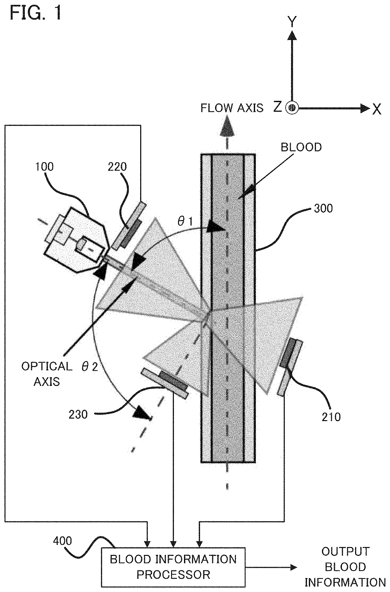
[0051]Firstly, a configuration of the measuring apparatus according to a first practical example will be explained with reference to FIG. 1. FIG. 1 is a plan view illustrating the configuration of the measuring apparatus according to the first practical example.

[0052]As illustrated in FIG. 1, the measuring apparatus according to the first practical example is configured as an apparatus for measuring a hematocrit value of blood by irradiating the blood that flows in a tubing 300, with light. The measuring apparatus is provided with an irradiator 100, a first light receiver 210, a second light receiver 220, a third light receiver 230, and a blood information processor 400.

[0053]The irradiator 100 is configured, for example, as a laser light source, and is configured to irradiate the blood that flows in the tubing 300, with light. The irradiator 100 is placed such that an optical axis of irradiation light is an angle of θ1 to a direction in which the blood flows (i.e., a flow axis in F...

second practical example

[0071]Next, a measuring apparatus according to a second practical example will be explained with reference to FIG. 7. FIG. 7 is a plan view illustrating a configuration of the measuring apparatus according to the second practical example.

[0072]The second practical example is partially different in configuration from the first practical example described above, and is substantially the same in other part. Thus, hereinafter, only a different part from the first practical example will be explained in detail, and an explanation of the same part will be omitted, as occasion demands.

[0073]As illustrated in FIG. 7, the measuring apparatus according to the second practical example is provided with two irradiators (which are specifically a first irradiator 110 and a second irradiator 120).

[0074]The first irradiator 110 is configured to apply light for measuring the transmitted light amount and the backscattered light amount. Thus, the first light receiver 210, which is configured to receive ...


PUM

PropertyMeasurementUnit
angleaaaaaaaaaa
angleaaaaaaaaaa
optical axisaaaaaaaaaa

Abstract

A measuring apparatus is provided with: an irradiator configured to irradiate fluid with light; a first light receiver configured to receive a forward scatter component of scattered light scattered by the fluid; a second light receiver configured to receive a backscatter component of the scattered light; a third light receiver configured to receive a side scatter component of the scattered light; and an outputting device configured to output fluid information about the fluid, which is obtained on the basis of light receiving signals of the first light receiver, the second light receiver, and the third light receiver. According to this measuring apparatus, it is possible to output accurate fluid information because of the use of the forward scatter component, the backscatter component, and the side scatter component of the scattered light.

Description

TECHNICAL FIELD[0001]The present invention relates to a measuring apparatus and a measuring method that can measure information about fluid, a computer program, and a recording medium.BACKGROUND ART[0002]For this type of apparatus, there is known an apparatus configured to irradiate fluid with light and to receive scattered light, thereby measuring information about the fluid. In the fluid, irradiation light is scattered in a plurality of directions. If those scattered lights are separately detected, it is considered that the information about the fluid can be measured by using respective properties of the scattered lights (e.g., refer to Patent Literature 1).CITATION LISTPatent Literature[0003]Patent Literature 1: Japanese Patent No. 4451567SUMMARY OF INVENTIONTechnical Problem[0004]The scattered light may include not only forward scattered light and backscattered light, but also side scattered light (i.e., light scattered in a direction substantially perpendicular to an optical ax...

Claims


Application Information

Patent Timeline
Patent Type & Authority Patents(United States)
IPC IPC(8): G01N21/53G01N33/49
CPCG01N21/532G01N33/49G01N2201/06113G01N2021/4769G01N2021/4711G01N2021/4709G01N2021/4707G01N2021/4726
Inventor KIKUCHI, IKUYAITO, ATSUYAKAGAWA, RYOHEIMURAKAMI, TOMOYAAGATA, AKARIADACHI, GENKI
Owner AIR WATER BIODESIGN INC
Why Eureka
Try Eureka