Method for locating phase faults in a microgrid

a micro-grid and phase fault technology, applied in the direction of fault location, fault location by conductor type, instruments, etc., can solve the problems of low short circuit current, low short circuit capacity of the inverter of these renewable resources, and inability to detect short circuit current by overcurrent protection devices,

Active Publication Date: 2021-12-28
SCHNEIDER ELECTRIC IND SAS
View PDF16 Cites 0 Cited by
  • Summary
  • Abstract
  • Description
  • Claims
  • Application Information

AI Technical Summary

Benefits of technology

[0009]It is an object of the invention to provide a method that allows to detect a phase fault in a microgrid in off-grid mode.

Problems solved by technology

The inverters of these renewable resources are characterized by low short circuit capacity.
When these installations operate in off-grid mode, the short circuit currents are low and cannot be detected by overcurrent protection devices—at least for some feeders.
However, phase faults, including both phase to phase faults, phase to neutral faults and three phase faults, remain undetected, presenting a risk of fire within few seconds.

Method used


Image

  • Method for locating phase faults in a microgrid
  • Method for locating phase faults in a microgrid
  • Method for locating phase faults in a microgrid

Examples


Embodiment Construction

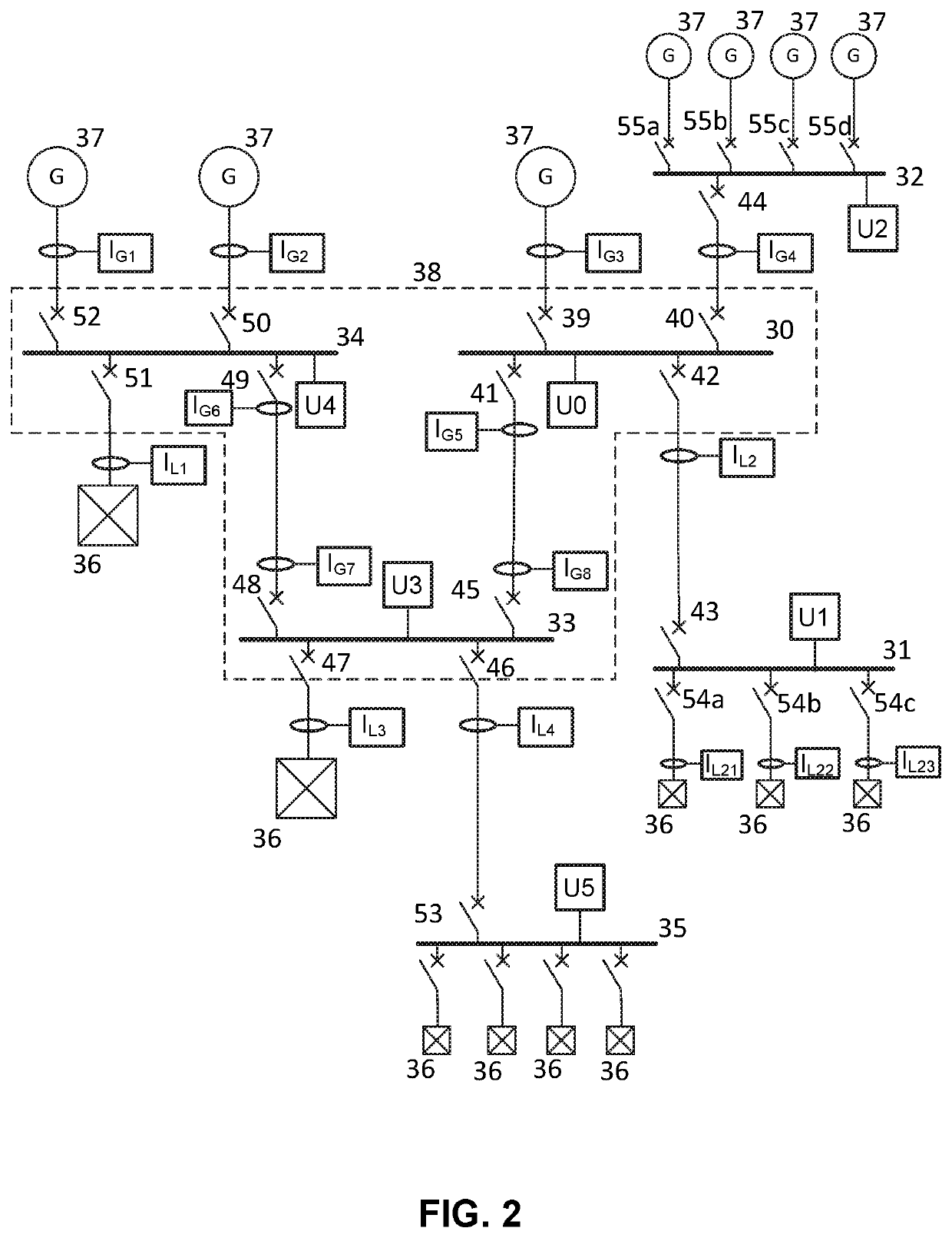
[0021]Referring to FIG. 2, a single line diagram is shown representing an example of a microgrid. The microgrid has six busbars 30-35 connecting various loads 36 and different energy resources 37. The energy resources 37 may be non-renewable, such as fueled generators, or renewable, such as photovoltaic cells. Each connection may be referred to as a feeder bay or feeder in short. The microgrid further has voltage measurement devices U0-U5 and current measurement devices indicated by IG1-IG4 for generator currents and IL1-IL4 and IL21-IL23 for load currents. Each current measurement device is associated with one feeder, being either incoming or outgoing. Each feeder may be connected and disconnected by a corresponding circuit breaker 39-52 from the respective busbar. For example, busbar 30 has one circuit breaker 39 controlling connection to one energy resource 37, one circuit breaker 40 controlling connection to busbar 32 connected to further energy resources 37, one circuit breaker...


PUM


Abstract

A method for locating and clearing phase faults in a micro-grid in off-mode. The method includes determining a surveillance area of a microgrid having at least two busbars to monitor; determining all source feeders and load feeders of the surveillance area; acquiring measurement data comprising current magnitude for all source feeders and load feeders; and monitoring the at least two busbars in the surveillance area for a voltage dip in one of phase-to-phase or phase-to-neutral voltages. The method further includes, on detecting a voltage dip on the monitored busbars, determining a defect phase having a minimum phase-to-neutral voltage; and performing current analysis for the defect phase.

Description

[0001]The present invention relates to a method for locating electrical faults in a microgrid, and in particular to a microgrid including distributed renewable and non-renewable energy sources.BACKGROUND[0002]A microgrid is basically a local electrical grid intended to generate and distribute electrical power in regions that are isolated and far from large electrical energy generation stations, such as, for example, islands, mountainous regions or desert areas. The microgrid principle is also applicable when it is desired for a building, neighborhood, campus or other entity connected to a wide distribution grid to manage the generation of its energy differently and e.g. increase its capacity for resilience. Thus, in general, a microgrid is an electrical installation integrating renewable and non-renewable energy sources and / or storage that is able to operate in both on-grid mode, that is connected to a utility grid, and in off-grid mode.[0003]Microgrids may be made up of various kin...

Claims


Application Information

Patent Timeline
Patent Type & Authority Patents(United States)
IPC IPC(8): G01R31/08H02H1/00H02H7/22H02H7/26
CPCG01R31/088G01R31/086H02H1/0007H02H7/22H02H7/26H02J3/381H02H3/28H02J13/00006H02J3/0012H02J2310/10H02J13/00034H02J13/0004Y04S10/12Y04S40/12Y02E40/70Y02E60/00
Inventor ALIBERT, PHILIPPEIGNATOVA, VANYA
Owner SCHNEIDER ELECTRIC IND SAS
Why Eureka
Try Eureka