Travel motion assist device

a technology of assist device and travel motion, which is applied in the field of travel motion assist device, can solve the problems of user feeling, small user's motion becomes, and the effect of user's motion on the interaction becomes smaller, and achieves the effect of high versatility and simple structur

Active Publication Date: 2022-01-04
HONDA MOTOR CO LTD
View PDF19 Cites 0 Cited by
  • Summary
  • Abstract
  • Description
  • Claims
  • Application Information

AI Technical Summary

Benefits of technology

[0030]The present invention thus provides a travel motion assist device which is simple in structure, is capable of assisting a travel motion of a user without causing any discomfort, and has a high level of versatility.

Problems solved by technology

Therefore, the stronger the assist force is, and the larger the mass, friction, and moment of inertia on the motion assist device is relative to those of the user, the smaller the user's motion becomes, and the smaller the effect of the user's motion on the interaction becomes.
Thus, when the control is performed based on the interaction force that changes according to the movement of the joint of the motion assist device, the user feels as if he or she is being forced to move by the motion assist device and may experience some discomfort.
The application point of the body weight of the user can be detected by providing the reaction force sensors on the toes and heels of the user's feet, but the gravitation center of the user cannot be accurately estimated from the detection data of the reaction force sensors.
If an assist force is applied based on the incorrectly identified center of gravity, the user may experience some discomfort in maintaining gait and balance.
Thus, although the motion assist device disclosed in Patent Document 3 can detect the timing of the grounding and lifting of the user's foot, and the drive motor can be driven based on the detected timing, the drive motor cannot be driven in a more correct timing different from the detecting timing.
Therefore, there is a significant restriction on the range of the assist mode to which the control can be applied so that the versatility of the motion assist device is limited.

Method used


Image

  • Travel motion assist device
  • Travel motion assist device
  • Travel motion assist device

Examples


second embodiment

[0109]A second embodiment of the present invention is described in the following with reference to FIGS. 14 to 16. In the following description, the parts corresponding to those in the first embodiment in terms of either configuration or function are denoted with like numerals without repeating the description of such parts.

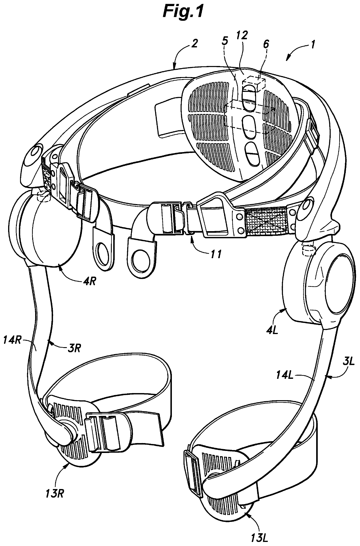
[0110]FIG. 14 is a side view of the walking motion assist device 101 of the second embodiment. As shown in FIG. 14, the walking motion assist device 101 is provided with a main frame 102 that is attached to the torso of the user U. The main frame 102 is connected to the left and right femoral frames 113 positioned along the respective femoral parts of the user U so that femoral frames 113 can be displaced around the respective hip joints of the user U. The lower end of each femoral frame 113 is connected to a leg frame 114 which is placed along the outer side of the corresponding lower leg of the user U so that the leg frame 114 can be displaced around the knee j...


PUM


Abstract

Provided is a travel motion assist device capable of assisting a travel motion of a user without causing any discomfort, and has a high level of versatility. A travel motion assist device includes an assist drive unit configured to be worn on a prescribed joint of the user required for the travel motion of the user, and to be driven in a corresponding manner, a torso motion detection unit configured to be worn on a torso of the user, and to detect the displacement of a center of gravity C indicating the movement of the torso, and a control unit configured to control an operation of the assist drive unit, wherein the control unit estimates a phase of the travel motion of the user according to a detection result of the torso motion detection unit, and drives the assist drive unit at a prescribed phase.

Description

CROSS-REFERENCE TO RELATED APPLICATIONS[0001]This application is a U.S. National Phase Application of PCT / JP2018 / 035493, filed Sep. 25, 2018, which claims the benefit of priority to JP Application No. 2017215247, filed Nov. 8, 2017, the contents of which are hereby expressly incorporated by reference in their entirety.TECHNICAL FIELD[0002]The present disclosure relates to a travel motion assist device configured to be worn by a user to assist the user's travel motion.BACKGROUND ART[0003]In recent years, there have been active research efforts on wearable motion assist devices for welfare and medical applications. A synchronization control is known as one of such control methods for such motion assist devices. The synchronization control is aimed at achieving a coordinated movement between the human and the device (see, for example, Patent Documents 1 and 2). In the synchronization control described in Patent Document 1, a phase acquisition unit is formed by an interaction force dete...

Claims


Application Information

Patent Timeline
Patent Type & Authority Patents(United States)
IPC IPC(8): A61H3/00A61H1/02B25J11/00
CPCA61H3/00A61H1/0244B25J11/008A61H2003/007A61H2201/163A61H2201/165A61H2201/1642A61H2201/5058B25J9/0006B25J13/088A61H2201/1207A61H1/0266A61H2201/5084A61H2205/088A61H2205/10A61H2205/12A61H2201/5007A61H1/0262
Inventor YASUHARA, KENIKEDO, YOSUKETAKENAKA, TORU
Owner HONDA MOTOR CO LTD
Why Eureka
Try Eureka