Accelerated methods and apparatuses for three-dimensional microscopy with structured illumination

a three-dimensional microscopy and structured illumination technology, applied in the direction of fluorescence/phosphorescence, instruments, optical elements, etc., to achieve the effect of reducing sample load and shortened measurement duration

Active Publication Date: 2022-01-11
CARL ZEISS MICROSCOPY GMBH
View PDF9 Cites 0 Cited by
  • Summary
  • Abstract
  • Description
  • Claims
  • Application Information

AI Technical Summary

Benefits of technology

[0010]The invention is based on the object of improving the methods and microscopes of the type mentioned in the introductory part such that the measurement duration can be shortened and the sample load can be reduced.
[0016]Instead, it can advantageously be used for calculating an image of an out-of-focus sample plane. All that is necessary in the case of a PSF that is typically mirror-symmetric with respect to the focal plane (and is typically rotationally symmetric about the optical axis of the detection) is to resolve the ambiguity of the depth information that results from the mirror symmetry. This is accomplished by using depth information from two different focal planes to reconstruct a sample plane that is located therebetween.
[0018]In this way, the number of the focal planes necessary for recording a z-stack can advantageously be reduced by selecting the distances between the focal planes to be greater than half a minimum axial distance that is optically resolvable by the microscope (that is to say corresponding to an axial resolution that is less than twice as fine compared to the optical resolution) and thereby initially formally violating the Nyquist-Shannon sampling theorem. By incorporating the additional (non-focused) sample planes in an approximate evaluation, the Nyquist-Shannon sampling theorem is effectively fulfilled. The additional sample planes can be considered to be “apparent” focal planes and be described as focal planes in the SIM system of equations. On account of the invention, the recorded focal planes can be situated for example with an axial distance of approximately 330 nm from one another, and yet it is possible to calculate complete resulting images of planes with an axial distance of only approximately 110 nm. Since, for each of the additional sample planes that have been included only by calculation (apparent focal planes), in each case a “real” focal plane can be omitted, the recording of individual images in a correspondingly large number of illumination phases is dispensed with. In this way, the measurement duration is significantly shortened and in the same way the sample is stressed less because it needs to be illuminated less frequently and consequently for a shorter time overall.
[0029]Expediently, a two-dimensionally spatially resolving detector is used to record the individual images, wherein in particular no stop that optically sections the sample is arranged in front of the detector. As a result, quick recording of the individual images is accomplished. Alternatively, confocal, scanning detection is possible.
[0030]Particularly preferred are embodiments in which the point spread function of the microscope is not manipulated for producing an axial asymmetry. This keeps the outlay in terms of apparatus low. In particular, it is possible in this way to dispense with a complex and costly phase mask.
[0031]Likewise particularly preferred are embodiments in which during the recording of each of the individual images only exactly one focal plane is focused. In this way, it is possible to dispense with complicated optics for simultaneously imaging a plurality of focal planes.

Problems solved by technology

However, no individual images of this additional sample plane are recorded (said additional sample plane is not focused) or in any event no individual images during the recording of which said additional sample plane is focused are used in the reconstruction of the resulting image.

Method used


Image

  • Accelerated methods and apparatuses for three-dimensional microscopy with structured illumination
  • Accelerated methods and apparatuses for three-dimensional microscopy with structured illumination
  • Accelerated methods and apparatuses for three-dimensional microscopy with structured illumination

Examples


Embodiment Construction

[0042]In all of the drawings, corresponding parts have the same reference signs.

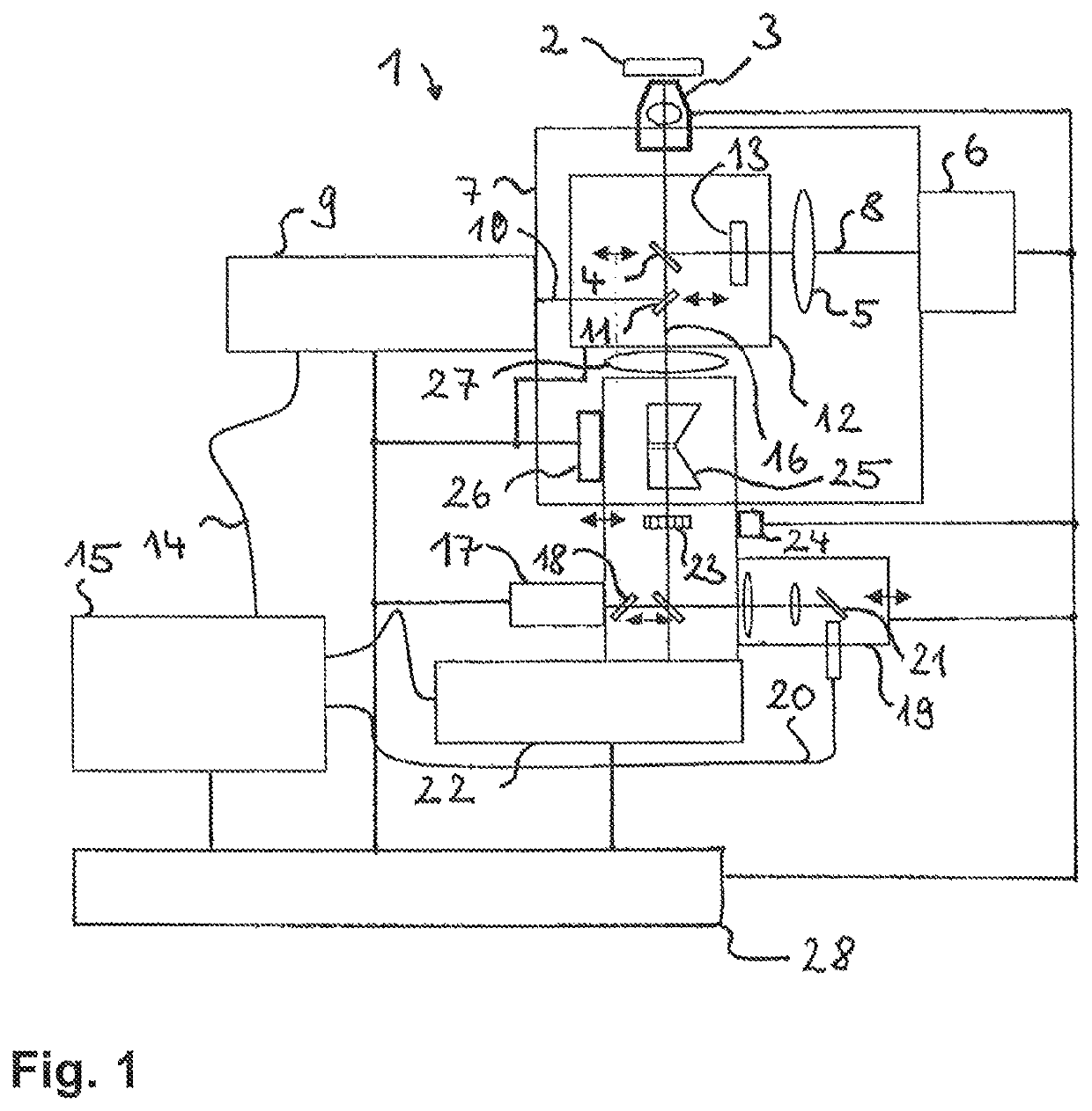
[0043]FIG. 1 shows a microscope 1 that is capable of performing both classical microscopy methods, that is to say microscopy methods the resolution of which is diffraction-limited, and super-resolution microscopy methods, that is to say microscopy methods the resolution of which goes beyond the diffraction limit.

[0044]The microscope 1 captures a sample 2. In addition, it has an objective 3 through which the radiation for all microscopy methods passes.

[0045]The objective 3 images, via a beam splitter 4, the sample together with a tube lens 5 on a CCD detector 6, which in the example is a generally possible area detector. To this extent, the microscope 1 has a conventional light microscope module 7, and the beam path from the sample 2 through the objective 3 and the tube lens 5 to the CCD detector 6 corresponds to a conventional widefield detection beam path 8. As indicated by the double-headed arrow in FI...


PUM

PropertyMeasurementUnit
axial distanceaaaaaaaaaa
distanceaaaaaaaaaa

Abstract

Accelerated methods and apparatuses for three-dimensional microscopy with structured illumination, in which focal planes of the sample are focused and each focal plane is illuminated in a plurality of phases sequentially with structured illumination light and the sample light emitted by the sample is recorded in a respective individual image. A resulting image having a resolution that is increased with respect to the individual images is reconstructed from the individual images to produce a super-resolved image stack, By reconstructing a resulting image from individual images of two different focal planes by approximation methods, said resulting image represents a sample plane that is situated between said focal planes, an image stack can be produced in a shorter period with less stress on the sample.

Description

RELATED APPLICATIONS[0001]The present application is a non-provisional application that claims priority to German Application No. DE 10 2018 009 056.7 filed on Nov. 12, 2018, the contents of which is hereby incorporated by reference in its entirety.FIELD OF THE INVENTION[0002]The invention relates to methods and apparatuses for imaging a sample using a microscope. When using the microscope, a focal plane of the sample is focused and the focal plane is illuminated in a plurality of phases sequentially with structured illumination light. The sample light emitted and / or scattered by the sample per phase is recorded using a detector in a respective (structured) individual image, such that a resulting image having increased (with respect to the individual images) resolution is able to be reconstructed from the individual images. Structured in this case means that the illumination light in the sample has at least one component with a constant spatial frequency.BACKGROUND OF THE INVENTION[...

Claims


Application Information

Patent Timeline
Patent Type & Authority Patents(United States)
IPC IPC(8): G02B21/00G01N21/64G02B21/06G02B21/36G06T17/00
CPCG01N21/6458G02B21/0076G02B21/06G02B21/361G06T17/00G01N21/6402G02B21/367G02B21/0032G02B27/58G02B21/008
Inventor KLEPPE, INGONOVIKAU, YAUHENI
Owner CARL ZEISS MICROSCOPY GMBH
Why Eureka
Try Eureka