
Vertical electroplating module and electroplating method for fan-out panel level chip

a technology of vertical electroplating and fan-out panel, which is applied in the field of electroplating, can solve the problems of only repurchase of the entire production line, increase maintenance trouble, waste of chemical medicine,

Active Publication Date: 2022-01-25
MANZ CHINA SUZHOU
View PDF4 Cites 0 Cited by
  • Summary
  • Abstract
  • Description
  • Claims
  • Application Information

AI Technical Summary

Benefits of technology

The patent describes a new technology that allows for conductive work without the need for a fixture, which reduces maintenance difficulties and eliminates waste of chemical medicine. The technology uses three pumps to transport and filter chemical medicine, with a second pump used to remove bubbles from the electroplating liquid. Additionally, there is a baffle to eliminate bubble issues in the electroplating process. Overall, this technology improves efficiency and reduces costs.

Problems solved by technology

Since the fixture will also be immersed in the chemical medicine, it will also be plated with copper, which not only wastes the chemical medicine, but also increases the trouble of maintenance.
Due to the current vertical electroplating capacity limitation, once the capacity demand increases, the entire production line can only be repurchased.

Method used


Image

  • Vertical electroplating module and electroplating method for fan-out panel level chip
  • Vertical electroplating module and electroplating method for fan-out panel level chip
  • Vertical electroplating module and electroplating method for fan-out panel level chip

Examples


Embodiment Construction

[0041]In order to explain the embodiments of the present disclosure or the technical solutions in the prior art more clearly, the following will briefly introduce the drawings that need to be used in the description of the embodiments or the prior art. Obviously, the drawings in the following description are merely present for some of the embodiments of the present disclosure, and for those of ordinary skill in the art, other drawings may be obtained based on these drawings without creative work.

[0042]The following will clearly and completely describe the technical solutions in the embodiments of the present disclosure with reference to the accompanying drawings in the embodiments of the present disclosure. Obviously, the described embodiments are only a part of the embodiments of the present invention, rather than all the embodiments. Based on the embodiments of the present disclosure, all other embodiments obtained by those of ordinary skill in the art without creative work shall ...


PUM

PropertyMeasurementUnit
electrical conductivityaaaaaaaaaa
conductiveaaaaaaaaaa
timeaaaaaaaaaa

Abstract

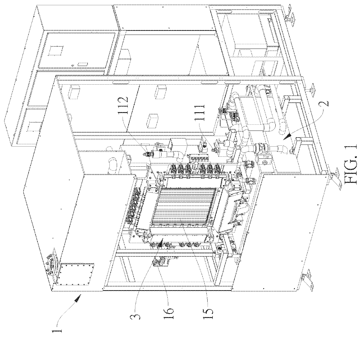
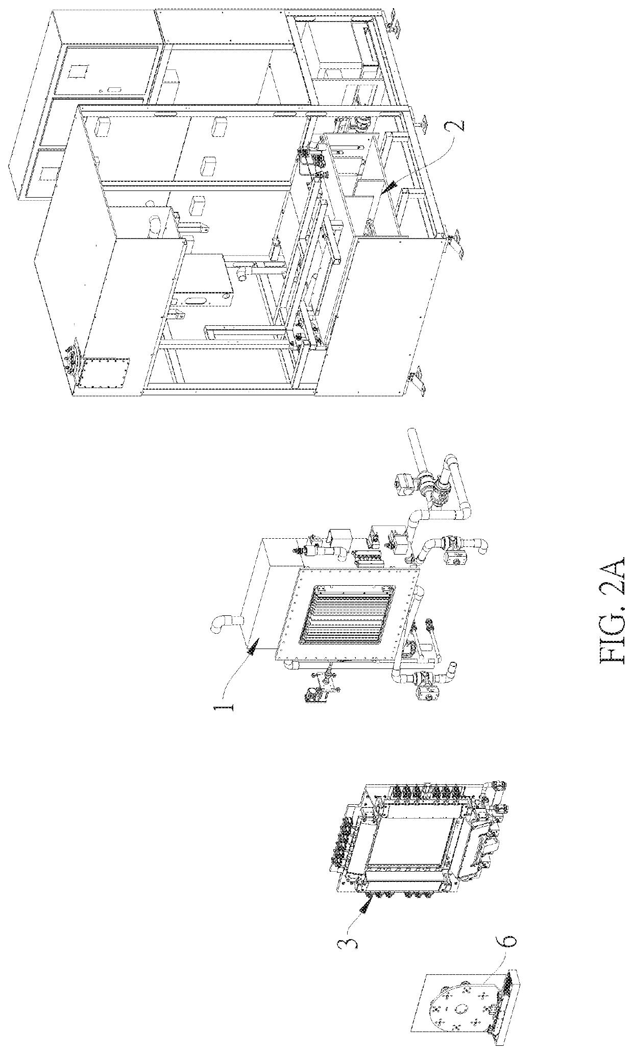
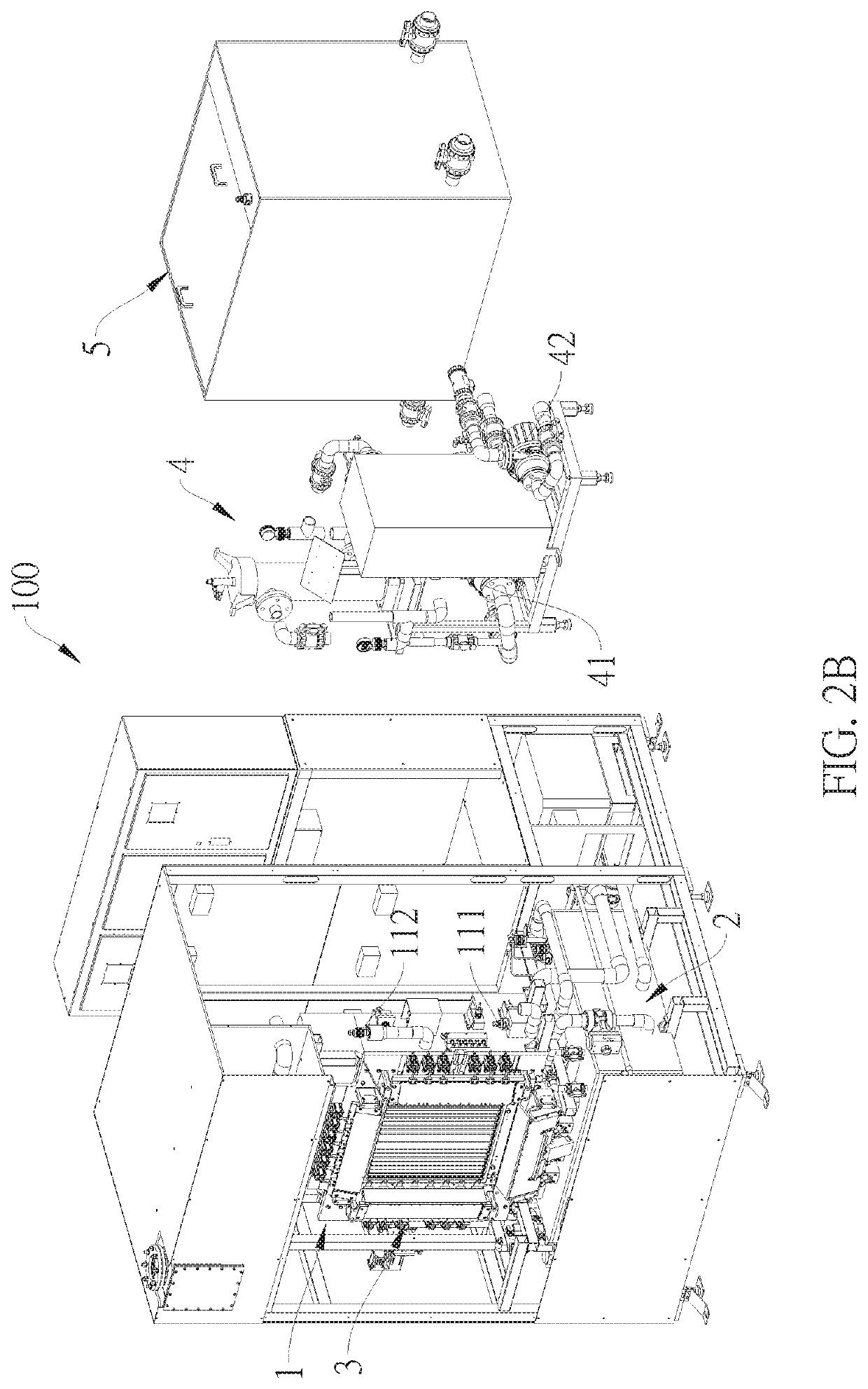
The present disclosure illustrates a vertical electroplating module and an electroplating method for a fan-out panel level chip. The vertical electroplating module has an electroplating tank module, an exhaust tank module and a clamping module. A first box of the electroplating tank module has a first receiving chamber, a second receiving chamber and a third receiving chamber, the first receiving chamber is communicated with a bottom of the second receiving chamber, and a top of the second receiving chamber is communicated with the third receiving chamber. The exhaust tank module is communicated with the first receiving chamber and the third receiving chamber respectively via a first pump and a second pump. The clamping module is disposed around the opening on a wall of the second receiving chamber. The production made by the vertical electroplating module can meet a single-side production, without immersing the entire product in the chemical medicine.

Description

TECHNICAL FIELD[0001]The present disclosure relates to an electroplating field, in particular to, a vertical electroplating module and an electroplating method for a fan-out panel level chip.RELATED ART[0002]A conventional vertical electroplating may be generally a gantry electroplating or a vertical continuous electroplating (VCP). The gantry electroplating is to clamp the product to the special fixture, and use the crane to soak the fixtures with the product into the tank one by one. During electroplating, the current is output to the fixture, and then conducted to the product board surface via the metal clamping point of the fixture, such that the copper ions in the chemical medicine are adhered to the production board to form the required copper.[0003]The Vertical continuous electroplating (VCP) is to clamp the product by using a specific jaw, use a drag chain to transport, and continuously soak the product into different tanks, clamp the product by using a specific fixture, and...

Claims


Application Information

Patent Timeline
Patent Type & Authority Patents(United States)
IPC IPC(8): C25D17/02C25D3/38C25D17/00
CPCC25D17/02C25D3/38C25D17/001C25D17/00C25D21/00C25D21/04C25D17/08C25D17/004C25D5/028C25D21/12C25D21/18C25D21/06Y02P10/20
Inventor WEN, WEI-CHUANYUAN, HONG-XING
Owner MANZ CHINA SUZHOU
Learn More