Flow control device for a storm water management system

a technology of storm water management and flow control, which is applied in the direction of valve operating means/releasing devices, functional valve types, sewage draining, etc., can solve the problems of low cost and land use requirements of many projects, and the performance of storm water management systems that do not approach the performance of ideal storm water management systems,

Active Publication Date: 2022-01-25
LANE ENTERPRISES
View PDF6 Cites 1 Cited by
  • Summary
  • Abstract
  • Description
  • Claims
  • Application Information

AI Technical Summary

Benefits of technology

[0101]Storm water regulations may allow for successively higher discharge rates as storms intensify. As a result, the ideal hydrograph may be a stepped curve on an outlet graph. The ideal hydrograph should be followed as closely as reasonably possible by the storm water management system to minimize storage system cost and size.
[0106]The step or discontinuous changes in effective flow area of the valve orifice generates the required step or discontinuous jumps in valve orifice discharge rate and effectively maintains the maximum allowed discharge rate for each storm portion 210a, 210b, 210c. This is why the shape of the valve body opening 200 is “irregular” (that is, not having a uniform constant width along its length and has step or discontinuous changes in width for generating step or discontinuous changes in discharge rate) so as to enable the valve to closely approximate the ideal outlet hydrograph shown in FIG. 18 in response to a storm event, and thereby minimizing the required system storage volume and related costs.

Problems solved by technology

Such storm water management systems do not approach the performance of an ideal storm water management system because they discharge water at a less than optimum rate when filling up.
Although these systems may better approach the ideal system than a simple fixed orifice system, their performance may still be lacking or their costs and land use requirements are prohibitive for many projects.
If the storm intensity exceeds a 50-year storm, the design of the storm water management system results in the storage chamber becoming full and unable to accept additional storm water at a rate exceeding the maximum discharge rate of the system.

Method used


Image

  • Flow control device for a storm water management system
  • Flow control device for a storm water management system
  • Flow control device for a storm water management system

Examples


first embodiment

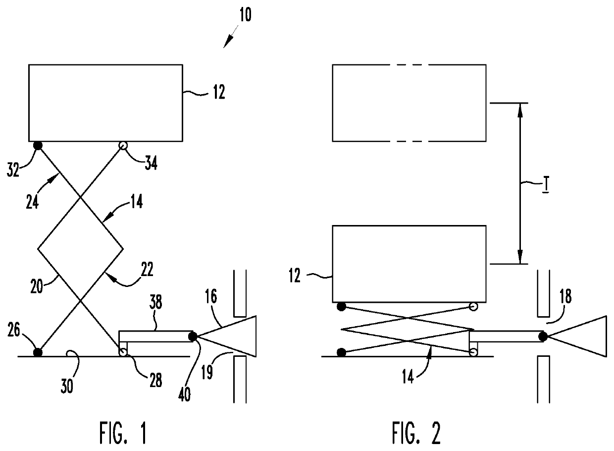
[0066]FIGS. 1 and 2 illustrate a portion of a first embodiment storm water management system 10 for managing storm water runoff. The system 10 is intended for placement in a storage chamber (not shown) that receives the storm water. A float 12 is attached to a scissors mechanism 14 that controls the location of a valve body 16 positioned in a chamber discharge 18. The valve body 16 and the discharge 18 cooperate to define a flow orifice 19 that discharges water from the storage chamber through the discharge 18.

[0067]The float 12 floats in the storm water and moves vertically up and down with changes in water level within the chamber. FIG. 1 illustrates the float 12 in a raised, uppermost position that occurs when the storage chamber is filled to maximum capacity. FIG. 2 illustrates the float 12 in a lowered, lowermost position that occurs when the storage chamber is essentially empty. The illustrated float 12 floats with the waterline centered between the top and bottom of the float...

second embodiment

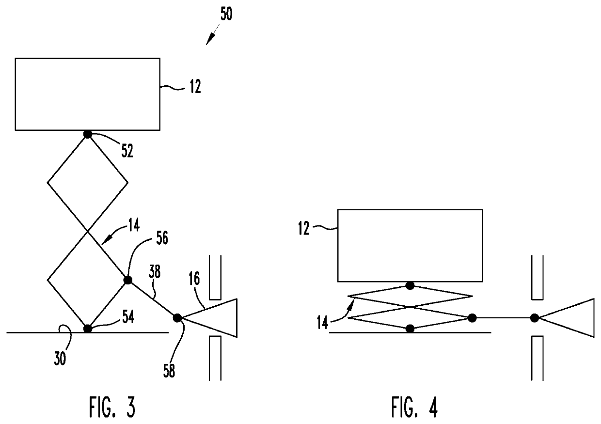
[0072]FIGS. 3 and 4 illustrate a portion of a second embodiment storm water management system 50. The system 50 is similar to the system 10 except that the scissors mechanism 14 is pinned to the float 12 at a pin connection 52 and is pinned to the chamber floor 30 at a pin connection 54. Arm 38 is pinned to the scissors pivot joint 56 and extends to a pin connection 58 connecting the arm to the valve body 16. In this embodiment the valve body 16 is constrained for horizontal movement only. Extension and contraction of the scissors mechanism 14 generates axial movement of the valve body 16 through displacement of the arm 38.

third embodiment

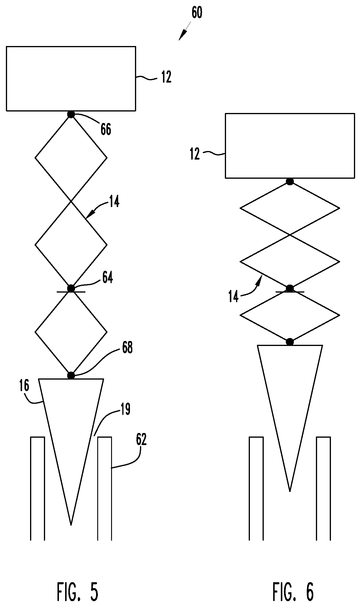
[0073]FIGS. 5 and 6 illustrate a portion of a third embodiment storm water management system 60 that controls the discharge of a vertical discharge pipe 62. An intermediate pin connection 64 of the scissors mechanism 14 is fixed to the storage chamber wall (not shown) against horizontal and vertical movement. The float 12 is attached to upper pin connection 66 and the valve body 16 is attached to lower pin connection 68. The valve body 16 cooperates with the intake end of the discharge pipe 62 to define the flow orifice 19. In this embodiment as the float rises the valve body moves downward towards the inlet end of the discharge pipe 62, reducing the flow area of the orifice 19. As the float descends the valve body moves upwards away from the inlet end of the discharge pipe 62, increasing the flow area of the flow orifice 19.

[0074]FIGS. 7, 8, and 9 each illustrate a storm water management system 70, 80, and 90 respectively, each system being similar to one another and to the storm w...


PUM


Abstract

A storm water management system includes a flow control device that includes a float in a storage chamber responsive to changes in water level and a valve disposed between the storage chamber and a discharge. The valve includes a relatively movable valving member connected to the float and a fixed valving member. Each valving member has a through opening that receives storm water flowing between the storage chamber and the discharge. The through-openings overlap one another whereby relative displacement of the valving members caused by float movement defines a variable-sized orifice between the storage chamber and the discharge that regulates the discharge rate of storm water from the system. The shapes of the overlapping openings enable the valve to closely follow the ideal output hydrograph and maximize the discharge rate as a function of storm intensity, thereby minimizing the required volume of the storage chamber.

Description

RELATED APPLICATION[0001]This application claims priority to and the benefit of U.S. Provisional Patent Application Ser. No. 62 / 542,398 “Flow Control Device for a Storm Water Management System” filed Aug. 8, 2017, which priority provisional patent application is incorporated by reference as if fully set forth herein.FIELD OF THE DISCLOSURE[0002]This disclosure relates to storm water management and in particular to a flow control device for a storm water management system.BACKGROUND OF THE DISCLOSURE[0003]Land development typically increases the peak flow rate of storm water runoff from a pre-development flow rate Q (cubic feet per second) as compared to a greater post-development peak flow rate Q′. A comparison of pre- and post-development hydrographs demonstrates not only the substantial increase in the peak flow rate from Q to Q′, but also that the post-development peak flow rate occurs substantially earlier in the storm event.[0004]Many jurisdictions require that storm water runo...

Claims


Application Information

Patent Timeline
Patent Type & Authority Patents(United States)
IPC IPC(8): F16K31/22F16K31/26F16K31/30E03F1/00F16K21/00
CPCE03F1/00F16K21/00F16K31/22F16K31/26F16K31/30F16K31/24
Inventor LANG, TIMOTHY JOELMILLER, KEVIN MARSHALL
Owner LANE ENTERPRISES
Why Eureka
Try Eureka