
Method of predicting occurrence of engine knocking

a technology of engine knocking and prediction method, which is applied in the direction of electric control, ignition automatic control, instruments, etc., can solve the problems of affecting the performance of the engine, and affecting the durability of the engin

Active Publication Date: 2022-02-01
SEOUL NAT UNIV R&DB FOUND
View PDF9 Cites 0 Cited by
  • Summary
  • Abstract
  • Description
  • Claims
  • Application Information

AI Technical Summary

Benefits of technology

The present patent is about a method for predicting engine knock and the occurrence of unburned gas in the engine using an estimated pressure in the cylinder and heat release rate. The method takes into account various operating parameters such as engine speed, intake and exhaust valve lifts, and valve timing. By calculating the initial pressure in the cylinder and the heat release rate for individual operating conditions, the method can predict the occurrence of knock and unburned gas with high accuracy. The method can also be used to optimize engine performance and reduce emissions.

Problems solved by technology

Knock may cause a rapid decrease in engine power, as well as engine overheating, failure of exhaust valves or pistons, melting problem of pistons and cylinders.
In addition, knocking combustion during driving a vehicle may cause noise to be transmitted to the vehicle cabin through the chassis, which cause driver's inconvenience, and cause damage to the engine, thereby impairing the engine durability.
However, the knock sensor detects vibration after knock occurs, and may not completely suppress engine block noise and damage caused by the knock.
The engine management system may impair the quietness and fuel efficiency of vehicle operation by rapidly changing operating parameters to avoid knocking combustion when the knock is detected.

Method used


Image

  • Method of predicting occurrence of engine knocking
  • Method of predicting occurrence of engine knocking
  • Method of predicting occurrence of engine knocking

Examples


Embodiment Construction

[0039]Reference will now be made in detail to exemplary embodiments of the present disclosure, examples of which are illustrated in the accompanying drawings. The present disclosure may, however, be embodied in different forms and should not be construed as limited to the embodiments set forth herein. In order to clearly illustrate the disclosure in the drawings, parts irrelevant to the description may be omitted in the drawings, and like reference numerals refer to like elements throughout the specification.

[0040]In the whole specification, it will be understood that when an element is referred to as being “connected” to another element, it can be “directly connected” to the other element or it can be “indirectly connected” to the other element with other elements being interposed therebetween. In addition, it will be understood that when a component is referred to as “comprising or including” any component, it does not exclude other components, but can further comprise or include ...


PUM

PropertyMeasurementUnit
pressureaaaaaaaaaa
absolute pressure sensoraaaaaaaaaa
heataaaaaaaaaa

Abstract

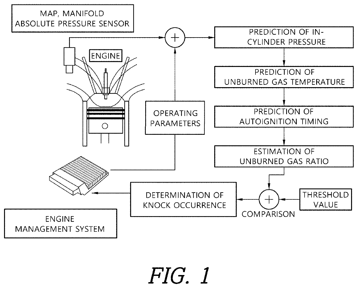
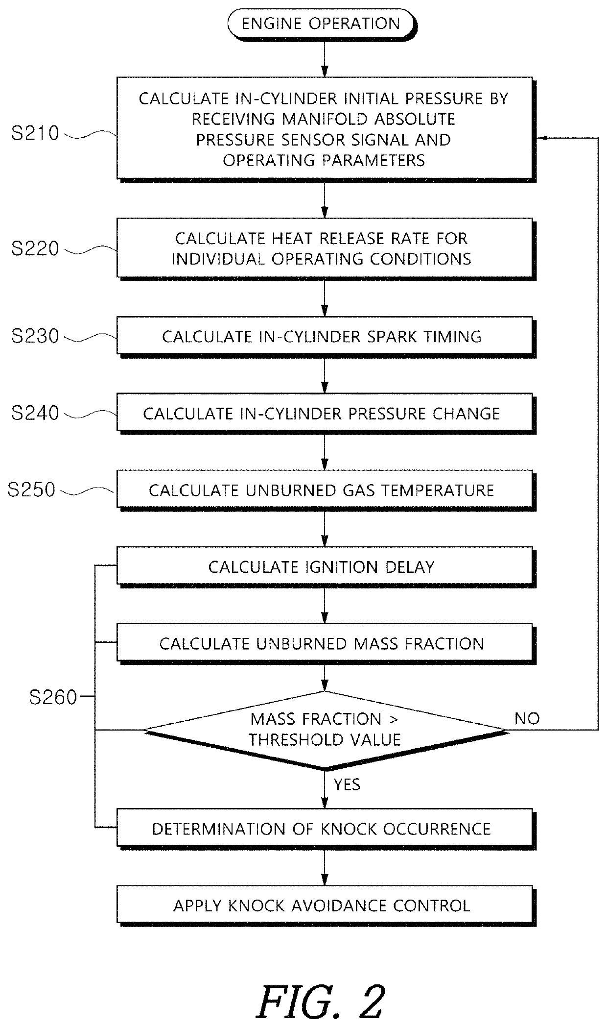
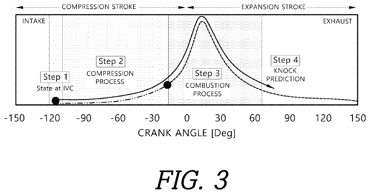
Disclosed herein is a method of predicting engine knocking, which includes calculating initial pressure in cylinder based on operating data and pressure in intake manifold measured using manifold absolute pressure sensor, calculating pressure at spark timing in the cylinder by interpreting compression process as polytropic process based on the calculated initial pressure in the cylinder, calculating heat release rate for individual operating conditions based on the calculated pressure in the cylinder at spark timing, calculating pressure change in the cylinder based on the calculated heat release rate, calculating unburned gas temperature in adiabatic compression process based on the calculated pressure change in the cylinder, and determining whether knock occurs by calculating ignition delay based on the calculated unburned gas temperature and calculating unburned gas mass fraction at crank angle at the end of the ignition delay.

Description

RELATED APPLICATIONS[0001]The present application is based on, and claims priority from, Korean Patent Application Number (10-2020-0046297), filed on Apr. 16, 2020, the disclosure of which is hereby incorporated by reference herein in its entirety.BACKGROUND1. Technical Field[0002]The present disclosure relates to a method of predicting engine knock(or knocking) phenomenon that occurs during vehicle operation.2. Related Art[0003]Knock means that mixture of gasoline and air is ignited by flame in engine cylinder to spread the flame to unburned mixture, in which time the unburned mixture spontaneously autoignites due to the rapid increase in pressure and temperature thereof. Knock may cause a rapid decrease in engine power, as well as engine overheating, failure of exhaust valves or pistons, melting problem of pistons and cylinders.[0004]In addition, knocking combustion during driving a vehicle may cause noise to be transmitted to the vehicle cabin through the chassis, which cause dri...

Claims


Application Information

Patent Timeline
Patent Type & Authority Patents(United States)
IPC IPC(8): G01L23/22F02D41/14F02D35/02F02D41/00F02P5/12
CPCF02D41/1401F02D35/023F02D35/024F02D35/025F02D35/026F02D41/009F02P5/12G01L23/221F02D2041/1412F02D2200/0406F02D2200/101Y02T10/40F02D2041/1433F02P5/152F02D35/027F02D45/00F02D13/0207
Inventor MIN, KYOUNG DOUGSONG, CHI HEONCHO, SEOK WONLEE, YOUNG BOKPARK, JI HWAN
Owner SEOUL NAT UNIV R&DB FOUND
Learn More