Method and system for particle characterization and identification

a particle characterization and particle technology, applied in the field of optical sensors, can solve the problem of imposing additional limits on the allowable pressure and temperature rang

Active Publication Date: 2022-02-01
HAL TECH LLC
View PDF4 Cites 2 Cited by
  • Summary
  • Abstract
  • Description
  • Claims
  • Application Information

AI Technical Summary

Problems solved by technology

The method used to fix the components together may impose additional limits on the allowable pressure and temperature range.

Method used


Image

  • Method and system for particle characterization and identification
  • Method and system for particle characterization and identification
  • Method and system for particle characterization and identification

Examples


Embodiment Construction

[0024]The above, as well as other objects and advantages of this disclosure, will become readily apparent to those skilled in the art from reading the following description of an embodiment of the invention. The description and drawings illustrate exemplary embodiments of the invention and serve to enable one skilled in the art to make or use the invention and are not intended to limit the scope of the invention in any manner. With respect to the methods disclosed and illustrated, the steps presented are exemplary in nature, and thus, the order of the steps is not necessary or critical.

[0025]As used herein, the terms “first”, “second”, “third”, and “fourth” may be used interchangeably to distinguish one component from another and are not intended to signify location or importance of the individual components.

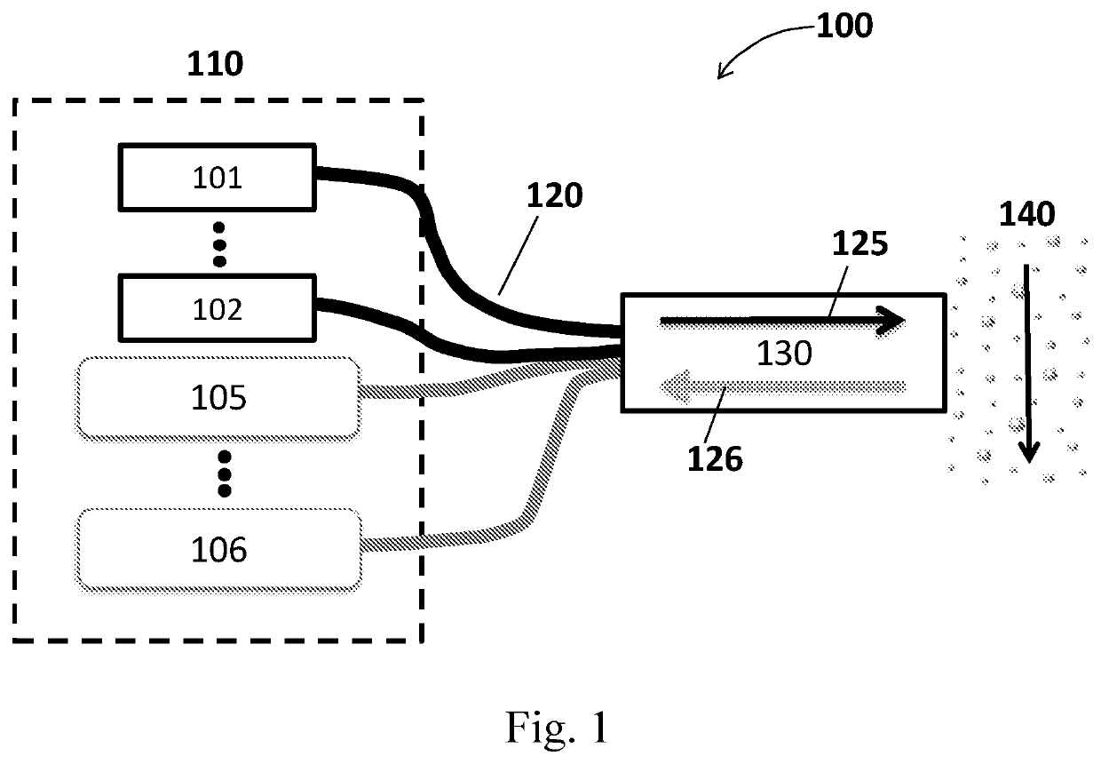
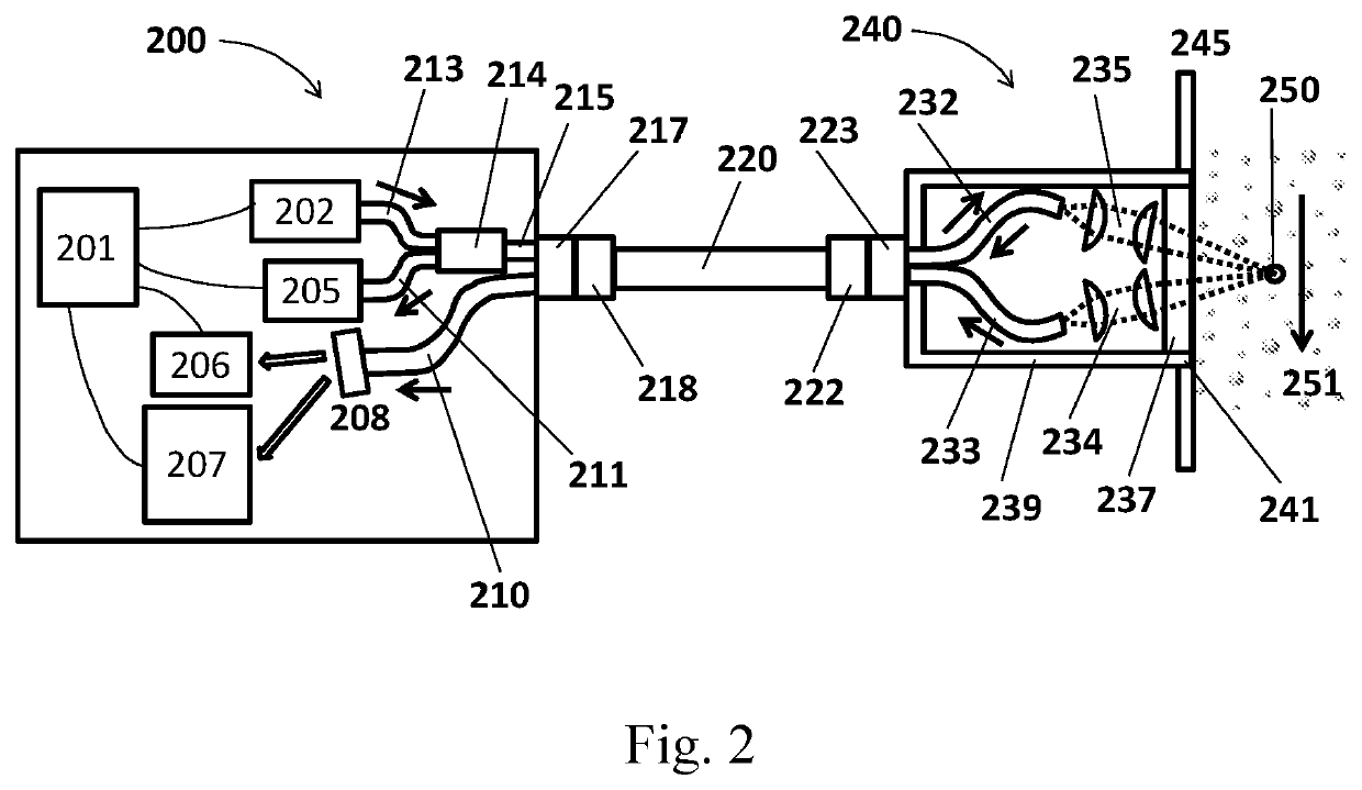
[0026]The present disclosure uses an in-situ approach wherein a sensor probe separates the light source(s), receiver(s), and electronics from the harsh measurement zone by using...


PUM

PropertyMeasurementUnit
temperatureaaaaaaaaaa
temperaturesaaaaaaaaaa

Abstract

Disclosed herein is a novel, compact, real time optical particle identification and characterization system and method of use within both gaseous and liquid media. The system can implement elastic and / or inelastic light scattering techniques simultaneously and complimentarily under the same sensor platform. By separating the sensing components from the electro-optical unit and using optical fibers for interconnection, only the sensing components need to be exposed to the environmental conditions. This reduces the design constraints on the electro-optical unit and permits the incorporation of optical components into the sensor probe that can withstand high-temperature, high-pressure, and corrosive environments. Thus, the system can be used in benign, moderate, and harsh environments.

Description

GOVERNMENT RIGHTS[0001]The invention described herein was made under U.S. Navy contract numbers N68335-14-C-0080, N68335-16-C-0499, and N68335-18-C-0388. The government may have rights under this invention.REFERENCES CITED[0002]U.S. Patent DocumentsDocument NumberDateNameUS ClassificationU.S. Pat. No. 10,139,329 B2November 2018OwenU.S. Pat. No. 9,714,967 B1July 2017Weickert et al.324 / 456US-2016 / 0313233 A1October 2016Zangmeister et al.356 / 416U.S. Pat. No. 8,582,089 B2November 2013Nelson et al. *356 / 73US-2013 / 01228705 A1September 2013Nishikawa et al. *250 / 459.1US-2010 / 0288921 A1November 2010Wang et al.250 / 287U.S. Pat. No. 7,675,619 B2March 2010Danehy et al.356 / 337U.S. Pat. No. 7,518,719 B2April 2009Sprenger et al 356 / 243.2US-2009 / 0039249 A1February 2009Wang et al.250 / 287U.S. Pat. No. 7,404,929 B2July 2008Fulghum, Jr. 422 / 82.05U.S. Pat. No. 7,260,483 B2August 2007Gard et al.702 / 22 U.S. Pat. No. 7,106,442 B2September 2006Silcott et al.356 / 338U.S. Pat. No. 7,072,038 B2July 2006Quist et a...

Claims


Application Information

Patent Timeline
Patent Type & Authority Patents(United States)
IPC IPC(8): G01N15/00G01N15/02G01N15/10
CPCG01N15/0205G01N2015/1087G01N15/1459G01N15/1434G01N2015/0046G01N21/85G01N21/65G01N21/53
Inventor LIN, HAIWALDHERR, GREGOR ARTHUR
Owner HAL TECH LLC
Why Eureka
Try Eureka