
Rolling bearing cage

a bearing cage and roller technology, applied in the direction of rolling contact bearings, shafts and bearings, rotary bearings, etc., can solve the problem of changing the resonance behavior of the passive resonant circui

Active Publication Date: 2022-02-15
AB SKF +1
View PDF12 Cites 0 Cited by
  • Summary
  • Abstract
  • Description
  • Claims
  • Application Information

AI Technical Summary

Benefits of technology

The present invention relates to a device with a conductive track embedded in a cage to detect wear on the cage caused by contact with a bearing surface. This helps to detect cage failure and prevent damage to the device.

Problems solved by technology

Thereby, a rupture in the cage main body ruptures the antenna coil, changing the resonance behavior of the passive resonant circuit.

Method used


Image

  • Rolling bearing cage
  • Rolling bearing cage

Examples


Embodiment Construction

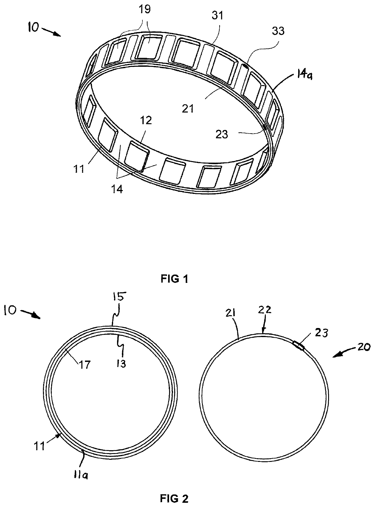
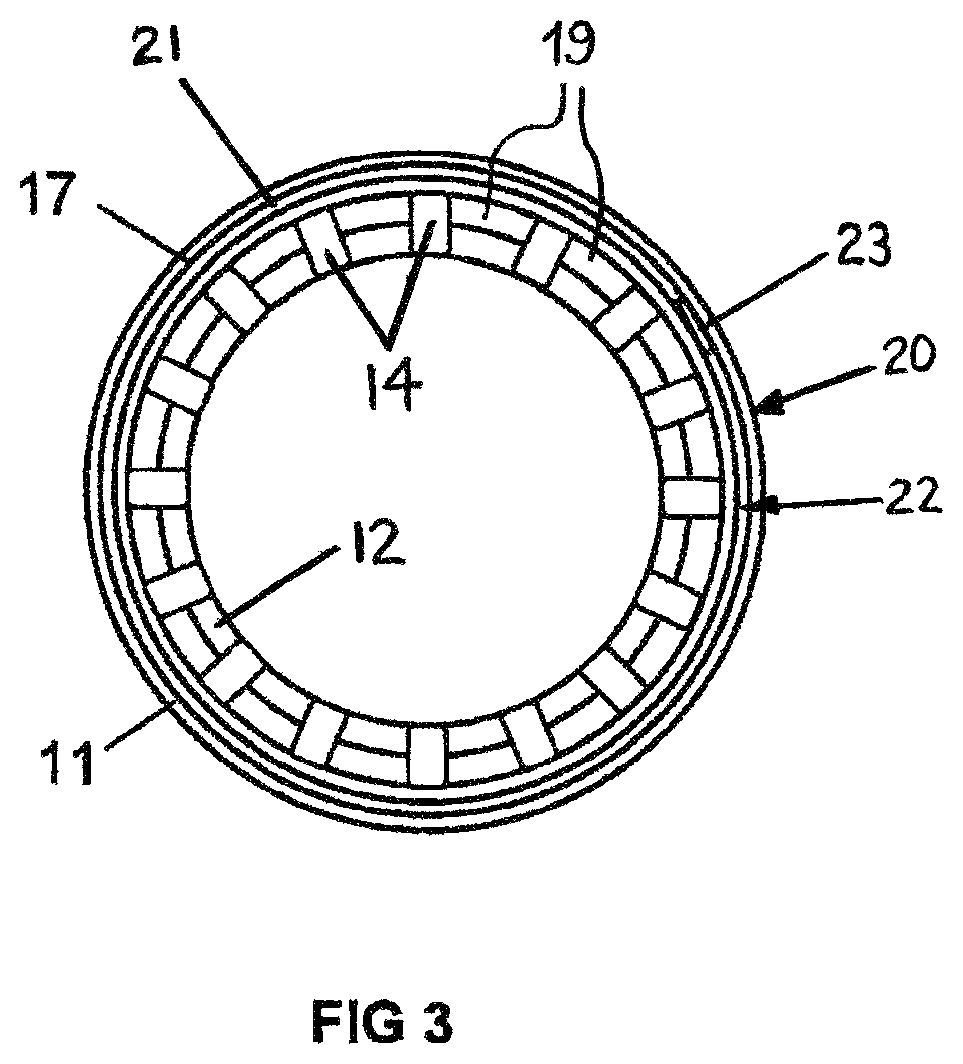
[0010]FIG. 1 schematically depicts a cylindrical roller bearing cage 10 as an exemplary embodiment of the present invention. The depicted cage 10 has a plurality of pockets 19 for receiving cylindrical rollers of a cylindrical roller bearing. The cage 10 has a base cage structure comprising a first cage side ring 11 and a second cage side ring 12, which are connected by a number of cage bars 14. Specifically, the number of cage bars 14 correspond to the number of pockets 19 and each pocket 19 is defined between each pair of adjacent bars 14. However, the bearing cage 10 may alternatively have a base cage structure that includes only a single cage side ring 11 and the plurality of bars 14 extending from the single cage side ring 11.

[0011]The bearing cage 10 further comprises a first conductive track 21 in or on an area of the outer, free side face 11a of the first cage side ring 11. Preferably, the cage 10 also has a second conductive track 31 in or on an area of the outer “jacket” o...


PUM


Abstract

A rolling bearing cage includes at least one cage side ring and a plurality of cage bars extending from the cage side ring so as to form a plurality of pockets, each pocket being defined between a separate pair of adjacent bars, for receiving rolling bodies of the rolling bearing. A cage breakage detection unit includes at least one conductive track and a module for wireless cage breakage monitoring. The cage has at least one recess, in which at least a prefabricated part of the cage breakage detection unit is inserted and fixed.

Description

CROSS-REFERENCE[0001]This application claims priority to German Patent Application No. 102019207643.2, filed May 24, 2019, the entire contents of which are fully incorporated herein by reference.BACKGROUND OF THE INVENTION[0002]The present invention relates to rolling bearings, and more particularly to cages for retaining rolling bodies of such bearings.[0003]DE 10 2016 218 897 A1 discloses a bearing cage including a cage main body made of a polymer material and having pockets for receiving at least one row of rolling elements of a bearing. The cage is provided with a passive resonant circuit including an antenna coil attached to the cage main body. The antenna coil is formed as a conductive layer directly attached to the cage material of the cage main body and is designed so to have a breaking point less than or equal to a breaking point of the cage material. Thereby, a rupture in the cage main body ruptures the antenna coil, changing the resonance behavior of the passive resonant ...

Claims


Application Information

Patent Timeline
Patent Type & Authority Patents(United States)
IPC IPC(8): F16C33/46F16C41/00F16C19/52
CPCF16C19/52F16C33/4623F16C41/002F16C2233/00F16C33/467F16C33/56F16C33/4676F16C41/008F16C33/38F16C33/4611F16C33/565
Inventor HEBRARD, YOANNLANG, DEFENGDIERMEN, JEROEN VAN
Owner AB SKF
Features
  • Generate Ideas
  • Intellectual Property
  • Life Sciences
  • Materials
  • Tech Scout
  • Unparalleled Data Quality
  • Higher Quality Content
  • 60% Fewer Hallucinations
Learn More