Flow meter

a flow meter and flow rate technology, applied in the field of flow meter, can solve the problems of disadvantageous amplification of interference signals, significantly difficult analysis of very weak voltage signals, etc., and achieve the effect of easy analyzability of measurement signals

Active Publication Date: 2022-03-15
SIKA DR SIEBERT & KÜHN GMBH & CO KG
View PDF9 Cites 0 Cited by
  • Summary
  • Abstract
  • Description
  • Claims
  • Application Information

AI Technical Summary

Benefits of technology

[0008]At the core of the invention lies a vortex amplification that can be used even with low flow rates of the fluid inside the measuring tube. One can assume that this effect is caused by the fact that the arrangement of at least one protrusion upstream of the bluff body leads to the formation of turbulences at the protrusion and that the turbulences formed at the protrusion separate from the protrusion and can amplify the vortices, generated at the bluff body, of a forming Karman vortex street. This results in a stronger load being exerted on the measuring body by the stronger vortices periodically separating from the bluff body.
[0010]A particularly good amplification effect is obtained when two protrusions are disposed at the inner wall in mutually opposite positions. If the bluff body extends vertically through the circular cross-section of the measurement chamber, the protrusions are located laterally in the measuring tube in a lateral arrangement. In this respect, the protrusions are preferably disposed diametrically opposite each other and the periodical formation of vortices at the bluff body is amplified, in equal measure, in both lateral directions, by the formation of greater vortices caused by the formation of pre-vortices at the protrusions.
[0011]A significant advantage of inducing a vortex amplification by means of the protrusions at the inner wall of the measuring tube is that the protrusions can be small and generate only a weak additional flow resistance, in particular because the flow rate of the fluid in the vicinity of the inner wall of the measurement chamber is already significantly lower than in the middle of the measurement chamber, for example. Thus, the flow rates of the fluid flowing against the protrusions are significantly lower than a nominal flow rate of the fluid.
[0012]As a rule, the measurement chamber has a cylindrical basic shape, which extends in a rotationally symmetrical manner around the longitudinal axis, wherein the protrusion or protrusions more specifically have a flow edge, which extends parallel to the vertical axis and thus parallel to the longitudinal direction of extension of the bluff body. When the fluid flows against the protrusions, still water areas are formed on the rear side of the flow edges, which lead to the formation of turbulences in the fluid, wherein the formed turbulences can significantly amplify the vortices at the bluff body. This amplification has a stronger impact on the measuring body, which results in a stronger signal strength of the measurement signal.

Problems solved by technology

The analysis of very weak voltage signals is thus made significantly more difficult as a result of low flow rates.
An electronic amplification of pressure sensors is also known, wherein interference signals are however also disadvantageously amplified.

Method used


Image

  • Flow meter
  • Flow meter

Examples


Embodiment Construction

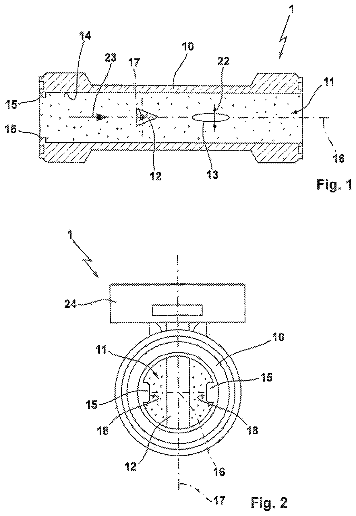
[0024]FIG. 1 shows a crosscut lateral view of a flow meter 1 with a measuring tube 10 for measuring the flow rate of a fluid that can flow through the measuring tube 10 in a flow direction 23. To this end, the measuring tube comprises a measurement chamber 11, which extends along a longitudinal axis 16 and comprises, for example, a circular flow cross-section. A bluff body 12, which extends along a vertical axis 17 is disposed inside the measurement chamber 11, wherein the vertical axis 17 is formed along the diameter of the measurement chamber, and the vertical axis 17 thus extends transversely to the longitudinal axis 16 and is thus vertical relative to the image plane.

[0025]The flow through the measurement chamber 11 occurs in a flow direction 23 indicated by an arrow, and a measuring body 13 is located downstream of the bluff body 12. Due to the fluid flowing against the bluff body 12, periodically separating vortices are formed thereon, which lead to a displacement of the measu...


PUM


Abstract

A flow meter for measuring the flow rate of a fluid, with a measuring tube that forms a measurement chamber through which the fluid can flow and with at least one bluff body that is disposed in the measurement chamber and wherein, additionally, a measuring body, which can be displaced due to the formation of vortices at the bluff body, is disposed downstream of the bluff body in the measurement chamber. The flow meter has at least one protrusion protruding into the measurement chamber and is formed upstream of the bluff body at an inner wall delimiting the measurement chamber.

Description

REFERENCE TO RELATED APPLICATION[0001]This application claims priority of German Patent Application DE 10 2018 101 278.0, filed Jan. 22, 2018, the entire content of which is incorporated herein by reference.FIELD OF THE INVENTION[0002]The invention relates to a flow meter for measuring the flow rate of a fluid, with a measuring tube, which forms a measurement chamber through which the fluid can flow and with at least one bluff body that is disposed in the measurement chamber and wherein, additionally, a measuring body, which can be deflected due to the formation of vortices, is disposed downstream of the bluff body in the measurement chamber.BACKGROUND OF THE INVENTION[0003]DE 198 82 239 B3, for example, discloses a flow meter for measuring the flow rate of a fluid, with a measuring tube, which forms a measurement chamber through which the fluid can flow and with at least one bluff body that is disposed in the measurement chamber and wherein, additionally, a measuring body, which ca...

Claims


Application Information

Patent Timeline
Patent Type & Authority Patents(United States)
IPC IPC(8): G01F1/32G01F15/14
CPCG01F1/3218G01F1/3209G01F15/14G01F1/32G01P5/01
Inventor ZANDER, STEFAN
Owner SIKA DR SIEBERT & KÜHN GMBH & CO KG
Why Eureka
Try Eureka