Electrical connector grounding structure

a grounding structure and connector technology, applied in the direction of coupling devices, two-part coupling devices, electrical equipment, etc., can solve the problems of reducing the stability of signal transmission, bandwidth and electronic signal quality that do not meet the standards, occupying space, and affecting the circuit layout, so as to improve the overall signal transmission stability and overall signal transmission quality. the effect of stability and reliability

Active Publication Date: 2022-03-29
ACES ELECTRONICS CO LTD
View PDF18 Cites 3 Cited by
  • Summary
  • Abstract
  • Description
  • Claims
  • Application Information

AI Technical Summary

Benefits of technology

[0006]The present invention has been accomplished under the circumstances in view. It is therefore the main object of the present invention to provide an electrical connector grounding structure, which comprises an electrically insulative housing, a conducting terminal sets, a conducting member and a shielding shell. The electrically insulative housing comprises a base, an accommodation hole located on the base, and a tongue plate extended from a front side of the base. The conducting terminal set comprises at least one grounding terminal, at least one power terminal and a plurality of signal terminals respectively positioned in the electrically insulative housing. The conducting member is positioned in the accommodation hole of the electrically insulative housing, comprising a first contact portion and a second contact portion extended from a bottom side of the first contact portion and disposed in contact with the at least one grounding terminal. The shielding shell comprises a docking space that accommodates the electrically insulative housing to keep the shielding shell in electrical contact with the first contact portion of the conducting member. Since the at least one grounding terminal of the conducting terminal sets, the conducting member and the shielding shell form a common ground loop to guide electromagnetic interferences (EMI) and noises generated around the electrical connector to the circuit board for grounding release, the electrical connector grounding structure can effectively suppress or filter electromagnetic interferences (EMI) and crosstalk interferences generated during signal transmission, thereby making the overall signal transmission quality more stable and reliable and achieving the effect of improving the overall signal transmission stability.

Problems solved by technology

Therefore, the size of the interface for transmitting electronic signals has been enlarged, but it has also taken up space and affected the circuit layout.
Nowadays, since the conductive metal conductors of the general-purpose serial bus interface are quite close in space, it is very easy to cause signal interference during high-frequency signal transmission due to the close proximity between adjacent conductive metal conductors during signal transmission (such as: electromagnetic wave interference, crosstalk interference, etc.), thereby reducing the stability of signal transmission.
Only when these conditions are met can the interference be effectively reduced, so that the signal transmission between the high-speed transmission interface and the system motherboard interface can be carried out correctly, otherwise, the signal transmission between the high-speed transmission interface and the system motherboard interface will produce signal reflections and cause loss, deformation and distortion of electronic signals, resulting in bandwidth and electronic signal quality that do not meet the standards, and affecting the normal operation of the electronic devices (such as: desktop computers, laptops or tablets, etc.).

Method used


Image

  • Electrical connector grounding structure
  • Electrical connector grounding structure
  • Electrical connector grounding structure

Examples


Embodiment Construction

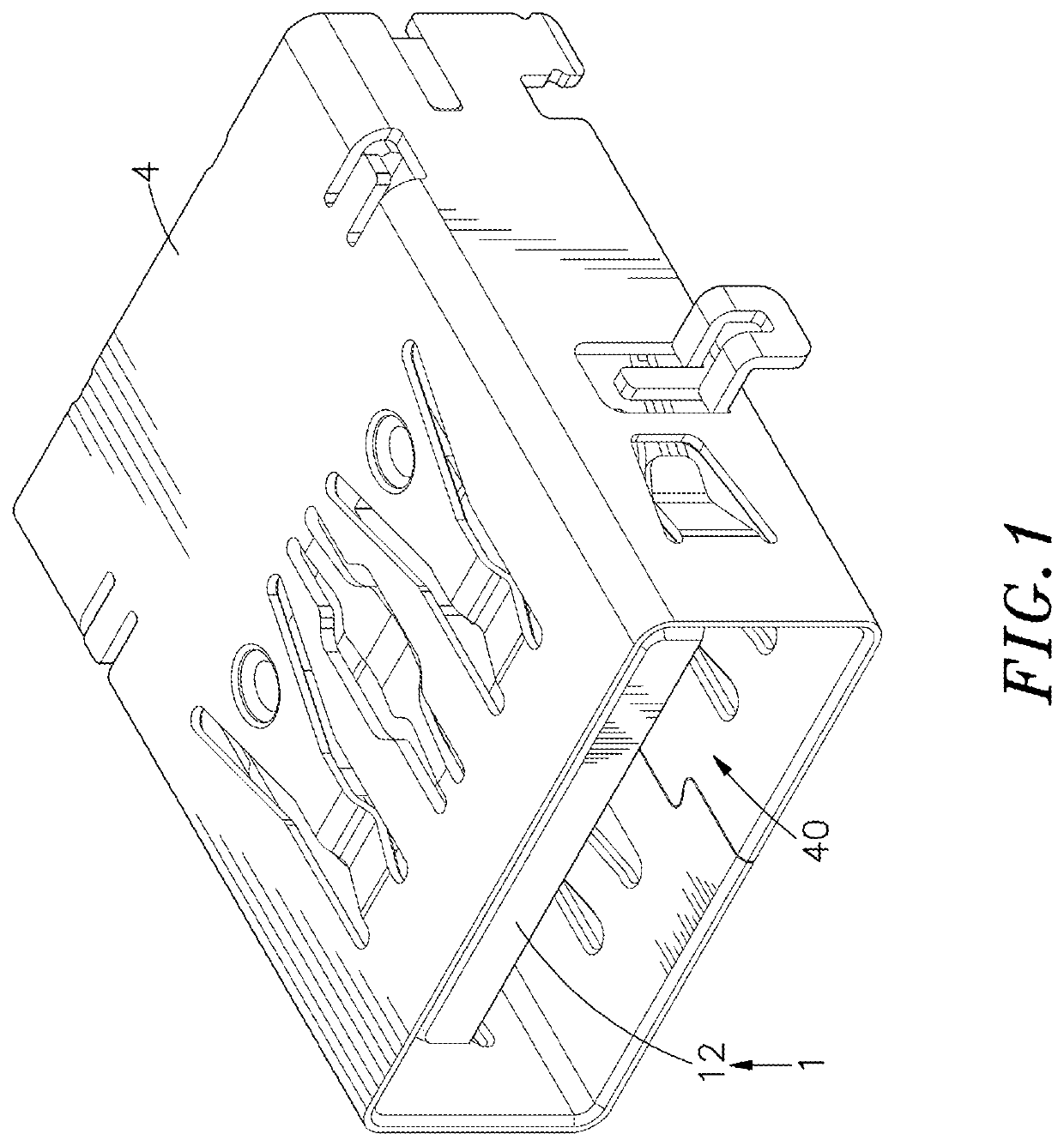
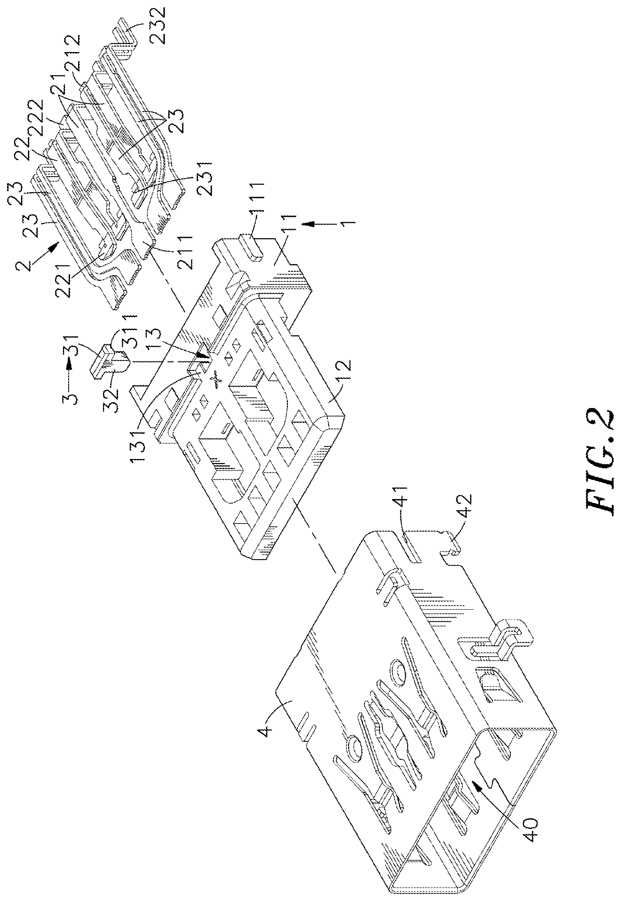
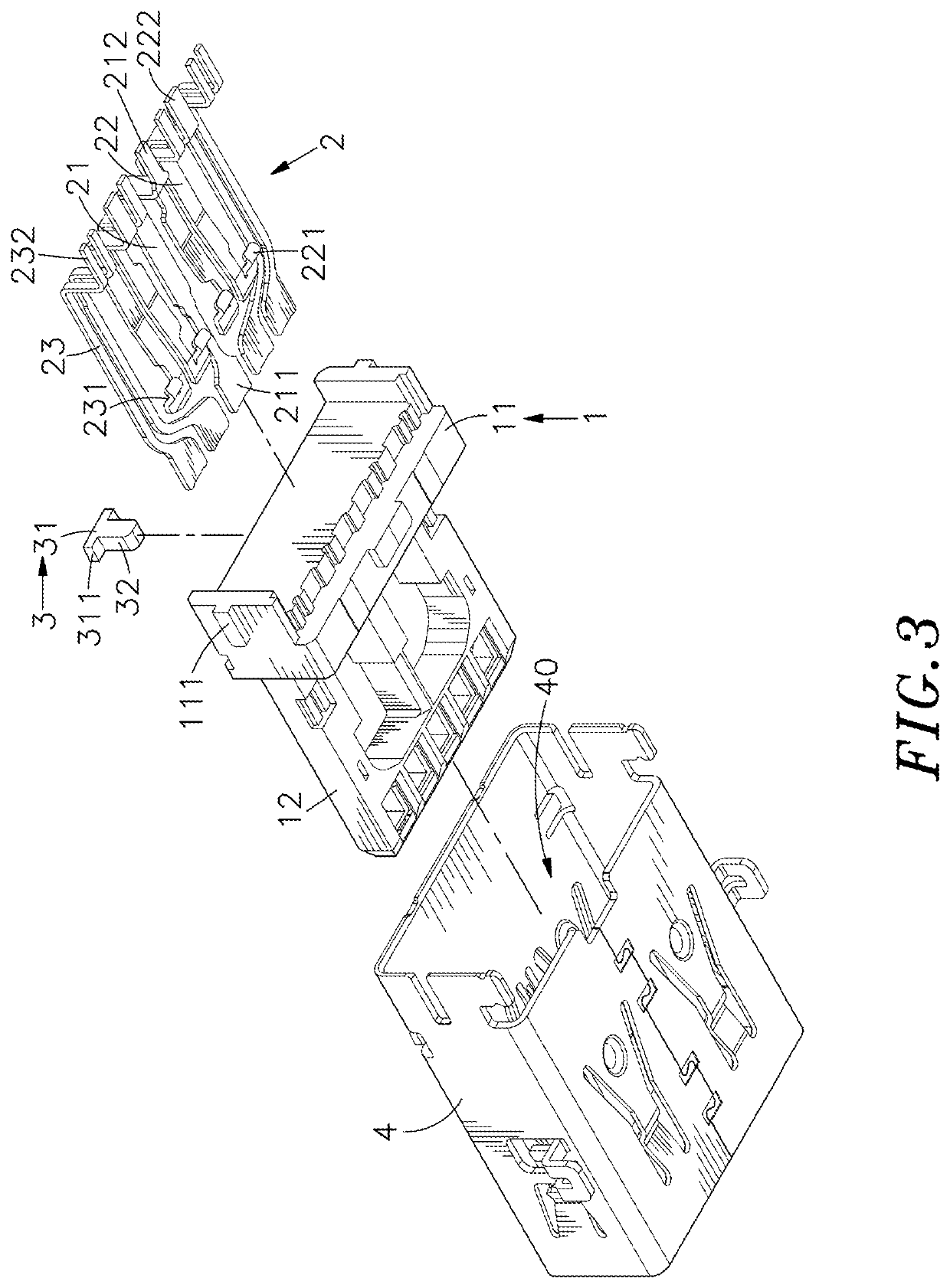
[0022]Referring to FIGS. 1-5, an oblique top elevational view of an electrical connector grounding structure in accordance with a first embodiment of the present invention, an exploded view of the electrical connector grounding structure of the first embodiment of the present invention, another exploded view of the electrical connector grounding structure of the first embodiment of the present invention when viewed from another angle, a sectional side view of the electrical connector grounding structure of the first embodiment of the present invention and another sectional side view of the electrical connector grounding structure of the first embodiment of the present invention are shown. As illustrated, the electrical connector grounding structure comprises an electrically insulative housing 1, a conducting terminal sets 2, a conducting member 3 and a shielding shell 4.

[0023]The electrically insulative housing 1 comprises a base 11, two retaining blocks 111 respectively located on ...


PUM


Abstract

Electrical connector grounding structure includes electrically insulative housing having accommodation hole located on base thereof and tongue plate forwardly extended from base, conducting terminal sets positioned in electrically insulative housing and including one or more than one grounding terminal, one or more than one power terminal and plurality of signal terminals, conducting member mounted in accommodation hole and having first contact portion located at top and second contact portion downwardly extended from first contact portion and kept in contact with grounding terminal, and shielding shell surrounding electrically insulative housing and kept in contact with first contact portion. Grounding terminal, conducting member and shielding shell form common ground loop to guide electromagnetic interferences and noises generated around electrical connector to circuit board for grounding release, making overall signal transmission quality more stable and reliable and achieving the effect of improving overall signal transmission stability.

Description

BACKGROUND OF THE INVENTION1. Field of the Invention[0001]The present invention relates to electrical connector technology, and more particularly to an electrical connector grounding structure, which uses at least one grounding terminal of a conducting terminal sets, a conducting member and a shielding shell form a common ground loop to guide electromagnetic interferences (EMI) and noises generated around the electrical connector to the circuit board for grounding release, thereby making the overall signal transmission quality more stable and reliable and achieving the effect of improving the overall signal transmission stability.2. Description of the Related Art[0002]As life enters the era of technology, there will be many appliances, or products around the living environment, which are affected by technology, and they are all toward the use of technology-based electronics. In the use of technological products, the operation and control methods of input signals are usually used to ...

Claims


Application Information

Patent Timeline
Patent Type & Authority Patents(United States)
IPC IPC(8): H01R13/6597H01R13/6581H01R13/6594
CPCH01R13/6597H01R13/6581H01R13/6594H01R24/62
Inventor TENG, CHANG-HOKUO, RONG-HSUNLIANG, CHIA-SHENG
Owner ACES ELECTRONICS CO LTD
Why Eureka
Try Eureka