Method and system for operating electrical energy stores

a technology of electrical energy and electrical energy, applied in the direction of battery/fuel cell control arrangement, electric devices, propulsion by batteries/cells, etc., can solve the problems of difficult parallel operation of accumulators of different ages or different sizes with a different cell chemistry, and achieve the effect of improving the validity of the present method, rapid switching, and increasing the accuracy of the present method

Active Publication Date: 2022-03-29
ROBERT BOSCH GMBH
View PDF13 Cites 0 Cited by
  • Summary
  • Abstract
  • Description
  • Claims
  • Application Information

AI Technical Summary

Benefits of technology

[0006]The advantage of the present invention is mainly to be seen in ensuring a parallel operation of energy stores without the use of wear-susceptible relays, heavy and expensive DC / DC converters or diode circuits causing power losses, the parallel operation in particular also allowing direct charging or the recovery of braking energy into the energy stores.
[0008]In view of a more rapid and flexible adaptation within the framework of the present invention, it may advantageously also be provided that an adaptation of an operation of at least one energy store is carried out with the aid of at least two semiconductor switches per energy store. The semiconductor switches may be integrated into the control unit.
[0009]Within the framework of a particularly resource-sparing execution of the present invention, a short-circuit detection may be provided in addition, and when a short circuit is detected, an adaptation of the operation of at least one energy store takes place with the aid of the control unit, in particular a deactivation of at least one energy store with the aid of the control unit. Within the framework of such a development, the current circuit in which the specific energy store is integrated may be checked for power dips on a permanent basis, and when a short circuit is detected, a rapid deactivation, especially through the use of semiconductor switches, may advantageously take place again so that the energy stores are protected by a rapid deactivation. A deactivation of short circuits is problematic especially when using relays for the deactivation, which may sustain irreversible damage on account of the high currents during a short-circuit. The deactivation time of relays or fuses, too, is often so long that very high currents and damage to the energy stores or their packaging may occur prior to the separation. For example, a short-circuit detection may be carried out with the aid of a device for short-circuit detection provided within the control unit and / or by a short-circuit deactivation. Alternatively, a short-circuit detection and / or short-circuit deactivation may also be carried out via conventional overcurrent protection devices such as safety fuses, electronic fuses or the like.
[0010]In addition, it may be provided within the framework of the method of the present invention that an adaptation of an operation of at least one energy store to an instantaneous driving profile of a motor vehicle takes place, the adaptation may be carried out on the basis of a comparison of the open-circuit voltages of the energy stores to an intermediate circuit voltage. According to the present method, two energy stores, for example, having different charge capacities, cell aging or cell chemistry are thereby able to be operated next to each other in an initial state. Within the framework of the ascertainment of an instantaneous power demand according to the present invention, different power demands may now be ascertained, for instance with regard to a current driving profile, and the operation of at least one energy store is able to be suitably adapted to the ascertained instantaneous power demands.
[0011]For example, given a low power demand, e.g., when a vehicle is traveling on a level road, an evaluation unit may ascertain, for example, the instantaneous charge capacities of the energy stores via the instantaneous cell voltage or the open-circuit voltage of the energy stores and compare it / them to an instantaneous intermediate circuit voltage. If it is then registered that the open-circuit voltage of the energy stores is greater than the intermediate circuit voltage, i.e. that EBat>EZK, then the operation is able to be adapted in that, for example, the semiconductor switch, which may be situated on the evaluation unit, switches the system accordingly so that the energy store having the higher open-circuit voltage, i.e. the energy store having the instantaneously greater charge capacity, supplies the system.

Problems solved by technology

For the same reason, a parallel operation of accumulators of different ages or different sizes with a different cell chemistry is also not easily possible.

Method used


Image

  • Method and system for operating electrical energy stores

Examples


Embodiment Construction

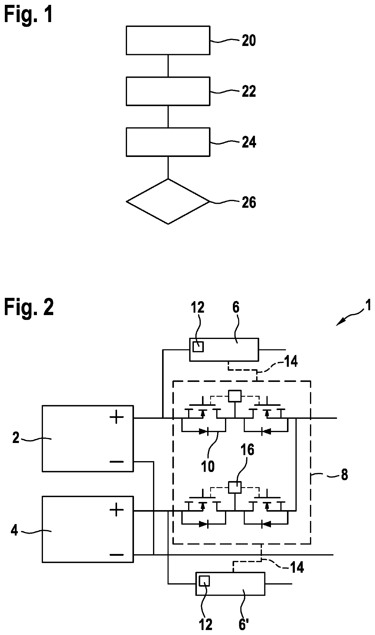
[0026]FIG. 1 shows a schematic representation of a method for operating electrical energy stores 2, 4 according to the present invention, in particular for use in motor vehicles, the method including the steps 20 through 26. In a first step of the method according to the present invention, an ascertainment 20 of a charge state of a first energy store 2 takes place at the outset with the aid of a first evaluation unit 6.

[0027]In a second step, which may be carried out simultaneously with the first step, an ascertainment 22 of a charge state of a second energy store 4 also takes place with the aid of a second evaluation unit 6′. In the process, the charge states of energy stores 2, 4 may alternatively also be ascertained using the same evaluation unit 6, 6′; the ascertainment 22, 24 of the charge states of energy stores 2, 4 may be carried out by a measurement of a current such as via a shunt or an open-circuit voltage or the like, for example.

[0028]In a third step of the method accor...


PUM


Abstract

A method for operating electrical energy stores, in particular for use in motor vehicles, the method including: ascertaining a charge state of a first energy store with the aid of an evaluation unit, ascertaining a charge state of a second energy store with the aid of an evaluation unit, ascertaining an instantaneous power demand with the aid of an evaluation unit, adapting an operation of at least one energy store on the basis of the ascertained charge states and the ascertained instantaneous power demand with the aid of a control unit, the adapting being made using at least one semiconductor switch, in particular bidirectionally.

Description

FIELD OF THE INVENTION[0001]The present invention is based on a method and to a system.BACKGROUND INFORMATION[0002]Methods and systems for optimizing a parallel operation of electrical energy stores are believed to be available from the related art.[0003]A parallel operation of a plurality of accumulators of the same type is meaningful in particular in order to scale an electrical range of vehicles. The charge states of the accumulators must be similar to one another for a parallel operation so that no large equalizing currents occur from one accumulator to the other. For the same reason, a parallel operation of accumulators of different ages or different sizes with a different cell chemistry is also not easily possible.SUMMARY OF THE INVENTION[0004]The subject matter of the present invention is a method having the features of the independent method claim as well as a system having the features described herein. Additional features and details of the present invention result from th...

Claims


Application Information

Patent Timeline
Patent Type & Authority Patents(United States)
IPC IPC(8): H02J7/00H02J7/14B60L58/22B60L50/60
CPCH02J7/0026B60L50/66B60L58/22H02J7/0014B60L58/12B60L58/21B60L3/0046B60L7/10Y02T10/70H02J7/0025H02J7/0048H02J2310/48
Inventor TEUSCH, STEFAN
Owner ROBERT BOSCH GMBH
Why Eureka
Try Eureka