
Syringe and plunger rod with stopper guide

a technology of syringe and guide rod, which is applied in the direction of intravenous devices, etc., can solve the problems of syringe leakage around the stopper, difficulty in handling and transportation of syringe, and care needs to be taken, so as to reduce the incidence of leakage

Active Publication Date: 2022-04-05
BECTON DICKINSON & CO
View PDF18 Cites 0 Cited by
  • Summary
  • Abstract
  • Description
  • Claims
  • Application Information

AI Technical Summary

Benefits of technology

The present invention is related to a syringe and plunger rod that reduces the likelihood of leakage between the two parts. This is achieved through the use of an annular plate or rib that stabilizes the plunger rod and maintains its position within the syringe barrel. The plunger rod also has multiple points of support that prevent distortion of the stopper and ensure the plunger remains on the same axis as the syringe barrel. Overall, the invention improves the stability and functionality of the syringe and plunger rod assembly.

Problems solved by technology

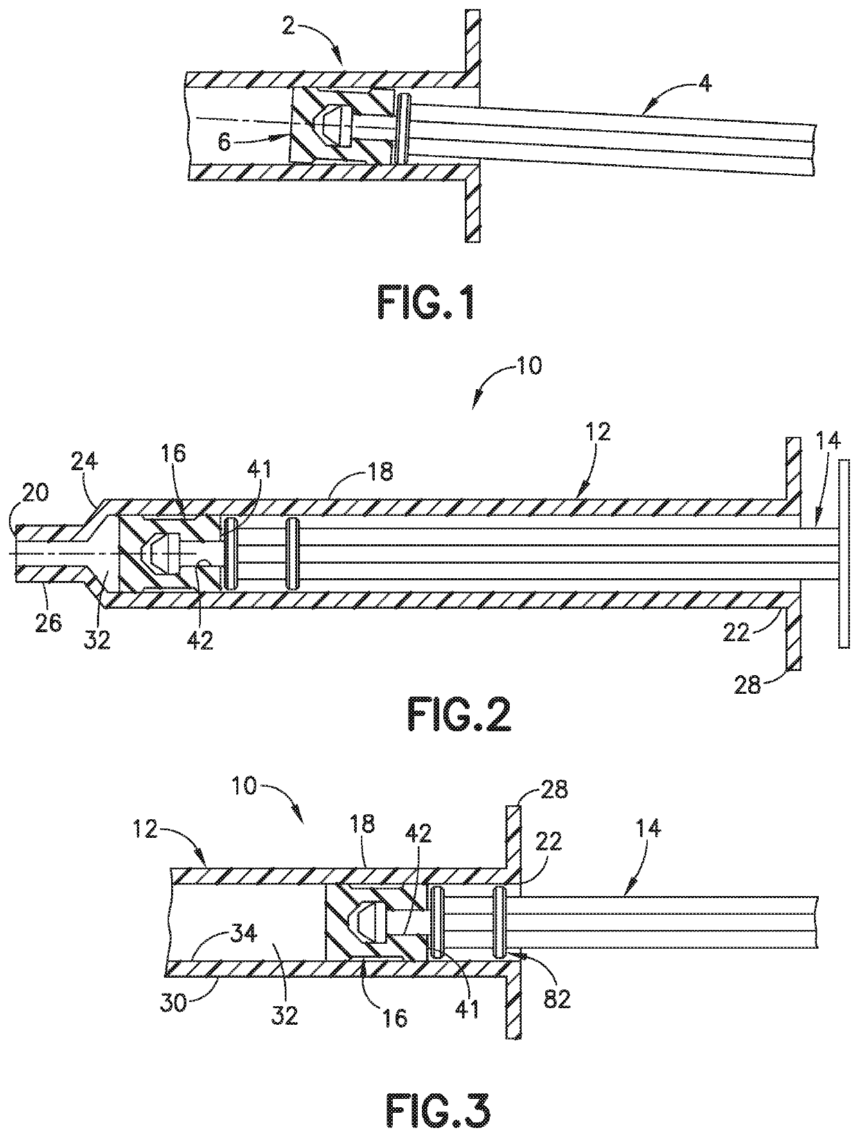
A side load or force applied at an inclined angle with respect to the direction of travel of the plunder rod can result in distortion of the stopper relative the syringe barrel that may result in leakage around the stopper.
The plunger that is protruding from the syringe barrel can make handling and transportation of the syringe difficult and special care has to be taken not to dislodge the plunger that can cause leakage.
When the plunger rod is withdrawn from the syringe barrel, the plunger rod may not be stable and can deflect to a position where the axis of the plunger rod is not aligned with the axis of the syringae barrel.
The stopper can be deflected at an angle that can cause leakage.

Method used


Image

  • Syringe and plunger rod with stopper guide
  • Syringe and plunger rod with stopper guide
  • Syringe and plunger rod with stopper guide

Examples


Embodiment Construction

[0031]Reference is made in detail to embodiments of the present invention, examples of which are illustrated in the accompanying drawings, wherein like reference numerals refer to the like elements throughout. The descriptions of these embodiments exemplify the present invention by referring to the drawings.

[0032]For purposes of the description hereinafter, the terms “upper”, “lower”, “right”, “left”, “vertical”, “horizontal”, “top”, “bottom”, “lateral”, “longitudinal”, and derivatives thereof shall relate to the invention as it is oriented in the drawing figures. However, it is to be understood that the invention may assume various alternative variations, except where expressly specified to the contrary. It is also to be understood that the specific devices illustrated in the attached drawings, and described in the following specification, are exemplary embodiments of the invention. Specific dimensions and other physical characteristics related to the embodiments disclosed herein a...


PUM


Abstract

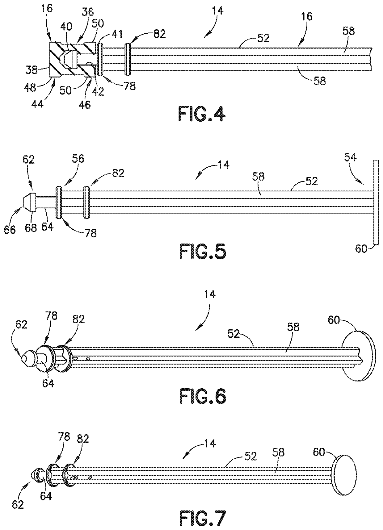
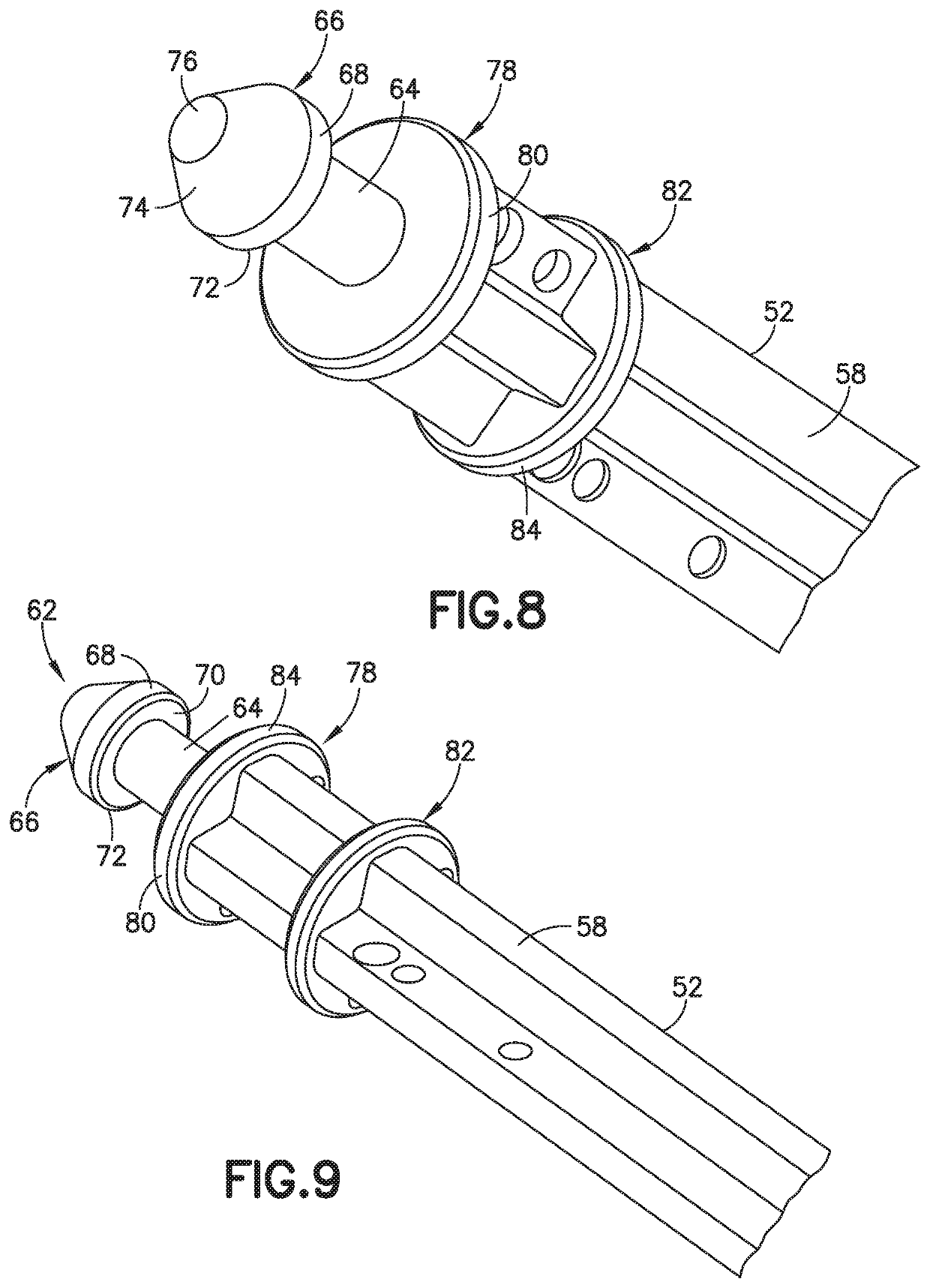
A syringe assembly (10) has a syringe barrel (12), a plunger rod (14) and stopper (16) where the syringe barrel has an open end receiving the plunger rod and stopper in a sliding direction. The plunger rod includes a shaft (52) having a longitudinal axis with a first end having a coupling member (62) for coupling with the stopper. The shaft has a least one plunger rod support (82) extending radially outer from the shaft and spaced from the first end for cooperating with an inner surface of the syringe barrel (12) to resist lateral movement and tilting of the plunger rod relative to the longitudinal axis of the axial passage of the syringe barrel. The shaft in one embodiment has at least two spaced apart points of support (41) and (82) for maintaining the axis of the plunger rod on axis with the syringe barrel to limit twisting and tilting of the stopper thereby resisting distortion of the stopper that can cause leakage.

Description

[0001]This application claims priority to U.S. Provisional Application No. 62 / 460,586 filed Feb. 17, 2017, which is hereby incorporated by reference in its entirety.FIELD OF THE INVENTION[0002]The present invention relates generally to a syringe and a plunger rod. The invention is particularly directed to a plunger rod provided with a stopper guide for assisting in maintaining a seal and preventing leakage when the plunge rod is off axis from the syringe barrel.BACKGROUND OF THE INVENTION[0003]Syringes are used for delivering a substance and for withdrawing and collecting arterial blood samples from the body of a patient. Various types of syringes have been devised that include a plastic or glass syringe barrel, a sealing elastomeric stopper, and a plunger rod. The syringes can include a self-sealing filter that allows passage of air out of the syringe during collection of a sample, while still preventing the passage of fluid being collected. This type of syringe having a filter all...

Claims


Application Information

Patent Timeline
Patent Type & Authority Patents(United States)
IPC IPC(8): A61M5/315
CPCA61M5/31513A61M5/31515
Inventor BOGERT, GERALDMONDRO, JASON RICHARDPRAIS, ALFRED WESLEY
Owner BECTON DICKINSON & CO
Learn More