Battery terminal with a star-point connection switch configuration for a vehicle electrical system

a technology of star-point connection switch and battery terminal, which is applied in the direction of secondary cell servicing/maintenance, battery, safety/protection circuit, etc., can solve the problems of inability to operate, adversely affect the subsequent start, and redundantly, so as to reduce the expenditure for line coupling

Active Publication Date: 2022-04-05
ROBERT BOSCH GMBH
View PDF9 Cites 0 Cited by
  • Summary
  • Abstract
  • Description
  • Claims
  • Application Information

AI Technical Summary

Benefits of technology

[0009]Two intelligent battery terminals represent the result of the substitution of one concentrated coupling / disconnecting element provided for coupling two safety-relevant (partial) vehicle electrical systems having increased requirements for the reliability of the disconnecting function, in conjunction with the successive elimination of its disadvantageous interaction properties.
[0025]The provided intelligent battery terminal in accordance with an example embodiment of the present invention enables in particular consumers or partial networks to be switched off without feedback, i.e., without adversely affecting the voltage supply in the remaining (partial) vehicle electrical system to be protected, in the event of overvoltage or undervoltage or overcurrent. Operating voltage limits of the consumers in the (partial) vehicle electrical system to be protected and the operating current limits of the lines in the defective partial networks are thus not violated.

Problems solved by technology

However, electrical consumers are still to be operable for a reasonable period of time in the turned-off state, without a subsequent start being negatively affected.
Furthermore, it is to be considered that in future activities external to driving are to be permissible to a limited extent in the case of highly-automated driving.
Energy supply and consumer may therefore be designed redundantly.
This may take place redundantly, which is also not possible upon use of a concentrated coupling / disconnecting element.
A concentrated coupling / disconnecting element may detect the voltage collapse and disconnect the previously coupled vehicle electrical systems; however, it cannot disconnect the fault current which loads one of the (partial) vehicle electrical systems even after its disconnection.

Method used


Image

  • Battery terminal with a star-point connection switch configuration for a vehicle electrical system
  • Battery terminal with a star-point connection switch configuration for a vehicle electrical system
  • Battery terminal with a star-point connection switch configuration for a vehicle electrical system

Examples


Embodiment Construction

[0033]The present invention is schematically illustrated with the aid of specific embodiments shown in the figures and is described in greater detail hereinafter with reference to the figures.

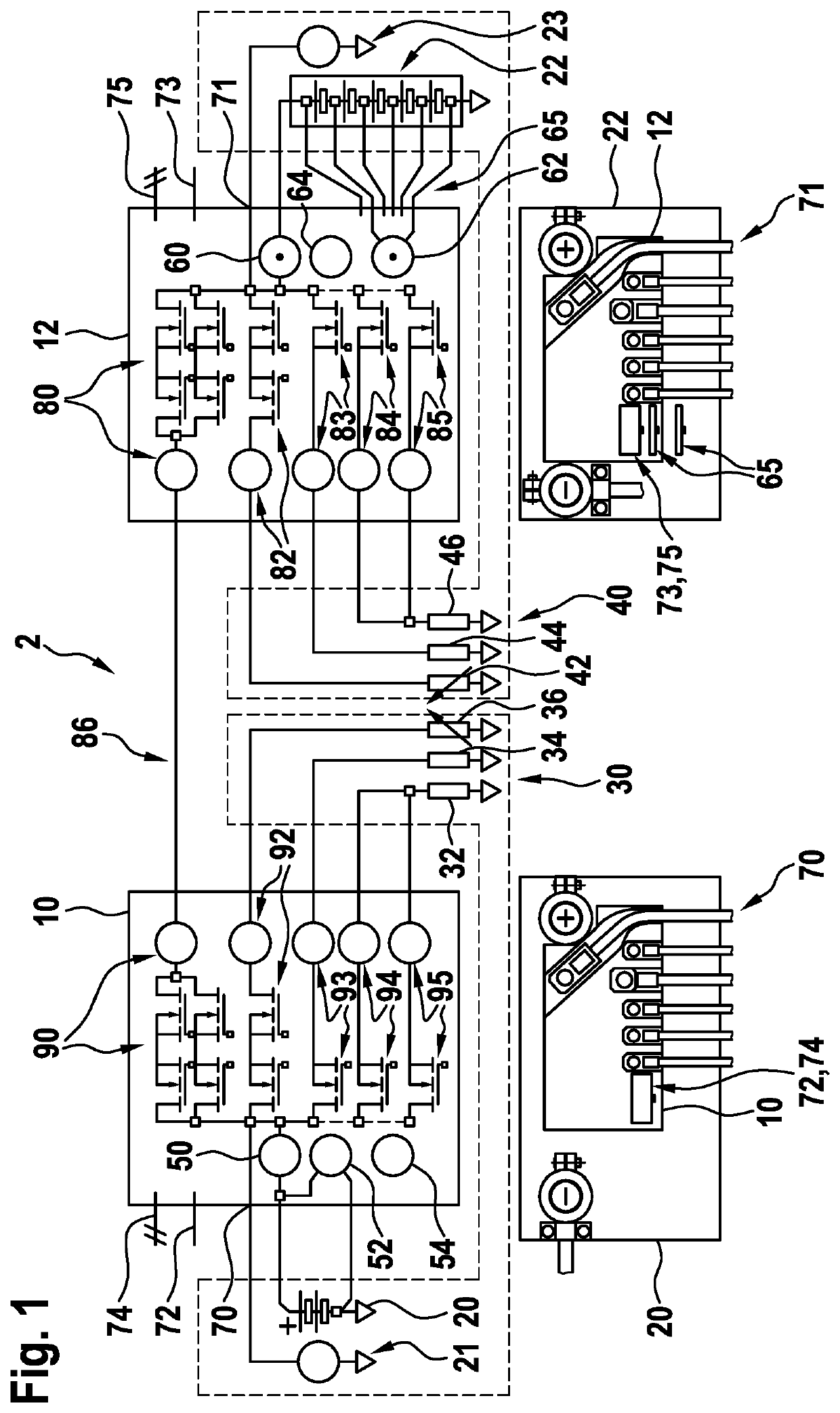
[0034]FIG. 1 shows an error-tolerant vehicle electrical system 2 made up of two coupled error-tolerant (partial) vehicle electrical systems 30, 40, the error tolerance of both (partial) vehicle electrical systems 30, 40 and of entire vehicle electrical system 2 being achieved by the use of provided intelligent battery terminals, namely by a first battery terminal 10 and a second battery terminal 12. The two battery terminals 10, 12 may also be referred to as intelligent battery terminals. First battery terminal 10 is provided for a first battery 20, for example, a lead acid battery here, and second battery terminal 12 is provided for a second battery 22, for example, a lithium-ion battery here including single cell contacts or BMS interface 65. Furthermore, first battery 20 is associated with f...


PUM

PropertyMeasurementUnit
distanceaaaaaaaaaa
power distributionaaaaaaaaaa
voltageaaaaaaaaaa

Abstract

A battery terminal which implements an electronically controlled vehicle electrical system coupling-disconnecting functionality including an electronically controlled power distribution, the battery terminal including a number of switching elements, of which at least some are connected to one another in a star point shape, the star-point connection being provided to be connected to a positive pole of a voltage source.

Description

FIELD[0001]The present invention relates to a battery terminal, which is in particular intelligent, for vehicle electrical systems, in particular for error-tolerant vehicle electrical systems, a vehicle electrical system including such a battery terminal, and a method for operating such a vehicle electrical system.BACKGROUND INFORMATION[0002]A vehicle electrical system is to be understood, in particular in automotive use, as the entirety of all electrical components in a motor vehicle. Therefore, both electrical consumers and supply sources, for example, generators or electrical accumulators, for example, batteries, are encompassed. Care has to be taken in the motor vehicle that electrical energy is available in such a way that the motor vehicle may be started at any time and a sufficient power supply is ensured during operation. However, electrical consumers are still to be operable for a reasonable period of time in the turned-off state, without a subsequent start being negatively...

Claims


Application Information

Patent Timeline
Patent Type & Authority Patents(United States)
IPC IPC(8): B60R16/033B60L58/10H01M10/42H02J7/00H01M50/543
CPCB60R16/033B60L58/10H01M10/425H01M50/543H02J7/0031H01M2010/4271H01M2220/20H02J7/0047H02J1/10Y02E60/10Y02T10/70
Inventor SCHILL, GEORGOWERFELDT, ANDRESHENOY, BASTI ANILKRONENBERG, BRITTAWOITE, GITAMOTZ, JUERGENBECKMANN, MARCOZABKA, MATTHIASDRAESE, NILSTIHOVSKY, SLAVALOTHSPEICH, TIMO
Owner ROBERT BOSCH GMBH
Why Eureka
Try Eureka