System and method for flexible recovery of argon from a cryogenic air separation unit

Active Publication Date: 2019-07-04
PRAXAIR TECH INC
View PDF4 Cites 0 Cited by
  • Summary
  • Abstract
  • Description
  • Claims
  • Application Information

AI Technical Summary

Benefits of technology

[0008]The present invention may be broadly characterized as an air separation unit comprising: (i) a main air compression system configured for producing a compressed and purified air stream, wherein the compressed and purified air stream is split into at least a first part of the compressed and purified air stream and a second part of the compressed and purified air stream; (ii) a booster compressor arrangement configured to further compress the first part of the compressed and purified air stream to produce a boosted pressure air stream; (iii) a main heat exchange system configured to cool the boosted pressure air stream and to partially cool the second part of the compressed and purified air stream; (iv) a turboexpander arrangement configured to expand the partially cooled second part of the compressed and purified air stream to form an exhaust stream, (v) a distillation column system having a higher pressure column and a lower pressure column linked in a heat transfer relationship via a condenser reboiler and an argon column arrangement operatively coupled with the lower pressure column, the distillation column system configured to receive a first portion of the boosted pressure air stream in the higher pressure column, a second portion of the boosted pressure air stream in the lower pressure column, and the exhaust stream in the higher pressure column or lower pressure column, wherein the exhaust stream imparts refrigeration to the distillation column system; and (vi) a nitrogen subcooler system having a plurality of valves, a header conduit or manifold, and a one or more heat exchanging cores, the nitrogen subcooler system configured to cool the clean shelf nitrogen stream and the dirty shelf nitrogen stream via indirect heat exchange with one or more nitrogen streams from the lower pressure column and produce a first nitrogen reflux stream comprised of clean shelf nitrogen, and a second nitrogen reflux stream comprised of dirty shelf nitrogen, and wherein a total nitrogen reflux stream is comprised of the first nitrogen reflux stream and the second nitrogen reflux stream. The recovery of the one or more oxygen products and the argon product from the air separation unit is adjusted by varying the percentage of dirty shelf nitrogen in the total nitrogen reflux stream.
[0009]The present invention may also be broadly characterized as a method of producing one or more oxygen products, one or more nitrogen products, and an argon product in an air separation unit, the method comprising the steps of: (a) producing a stream of compressed and purified air in a main air compression system; (b) splitting the stream of compressed and purified air into at least a first part of the compressed and purified air stream and a second part of the compressed and purified air stream; (c) further compressing the first part of the compressed and purified air stream in a booster compressor arrangement to produce a boosted pressure air stream; (d) cooling the boosted pressure air stream and partially cooling the second part of the compressed and purified air stream in a main heat exchange system; (e) expanding the partially cooled second part of the stream of compressed and purified air stream in a turboexpander arrangement to form an exhaust stream; (f) rectifying the boosted pressure air stream, the exhaust stream, and the second part of the compressed and purified air stream in a distillation column system to produce the one or more oxygen products, the one or more nitrogen products, and the argon product; (f) extracting a clean shelf nitrogen stream from the distillation column system and a dirty shelf nitrogen stream from the higher pressure column; (g) directing the clean shelf nitrogen stream and the dirty shelf nitrogen stream to a nitrogen subcooler system and cooling the clean shelf nitrogen stream and the dirty shelf nitrogen stream in the nitrogen subcooler system via indirect heat exchange with one or more nitrogen streams from the lower pressure column to produce a first nitrogen reflux stream comprised of clean shelf nitrogen, and a second nitrogen reflux stream comprised of dirty shelf nitrogen, and wherein a total nitrogen reflux stream is comprised of the first nitrogen reflux stream and the second nitrogen reflux stream. The recovery of the one or more oxygen products, one or more nitrogen products, and argon products from the air separation unit is adjusted by varying the percentage of dirty shelf nitrogen in the total nitrogen reflux stream.
[0010]In some embodiments, the cryogenic air separation unit may operate in a ‘no-argon’ or ‘low-argon’ mode when argon demand is low or non-exist

Problems solved by technology

While most cryogenic air separation units have a design life of several decades or more, the argon production requirements over the life of the cryogenic air separation unit often will vary, and such variance can be significant.
In addition, changes in local or regional argon product demand may also occur over the operational life of the cryogenic air separation unit.
For example, a local or regional market may be saturated with excess argon capacity or argon over-supply for extended periods of time in which full production of argon product is not warranted.
Conversely, such local or regional

Method used


Image

  • System and method for flexible recovery of argon from a cryogenic air separation unit
  • System and method for flexible recovery of argon from a cryogenic air separation unit
  • System and method for flexible recovery of argon from a cryogenic air separation unit

Examples


examples

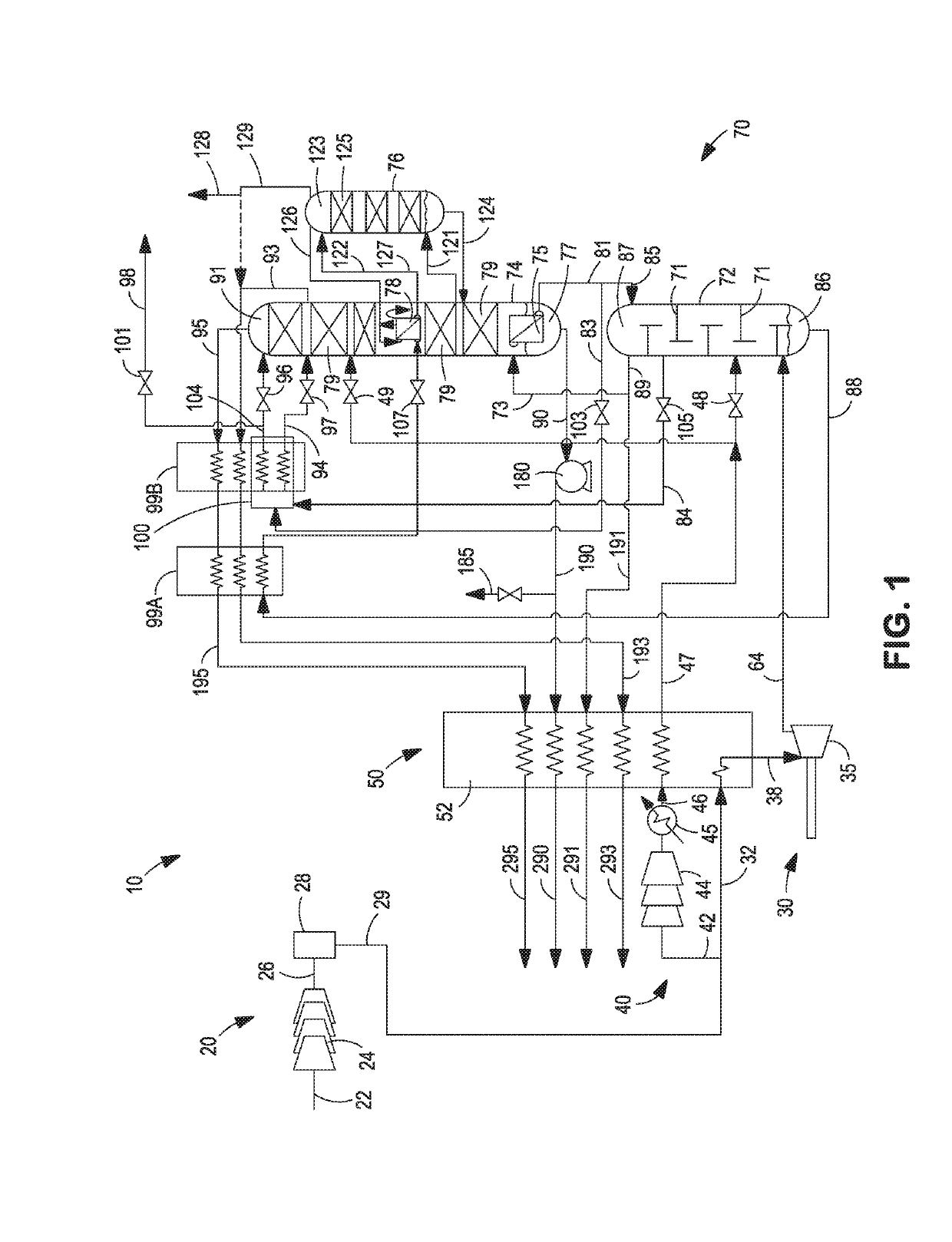
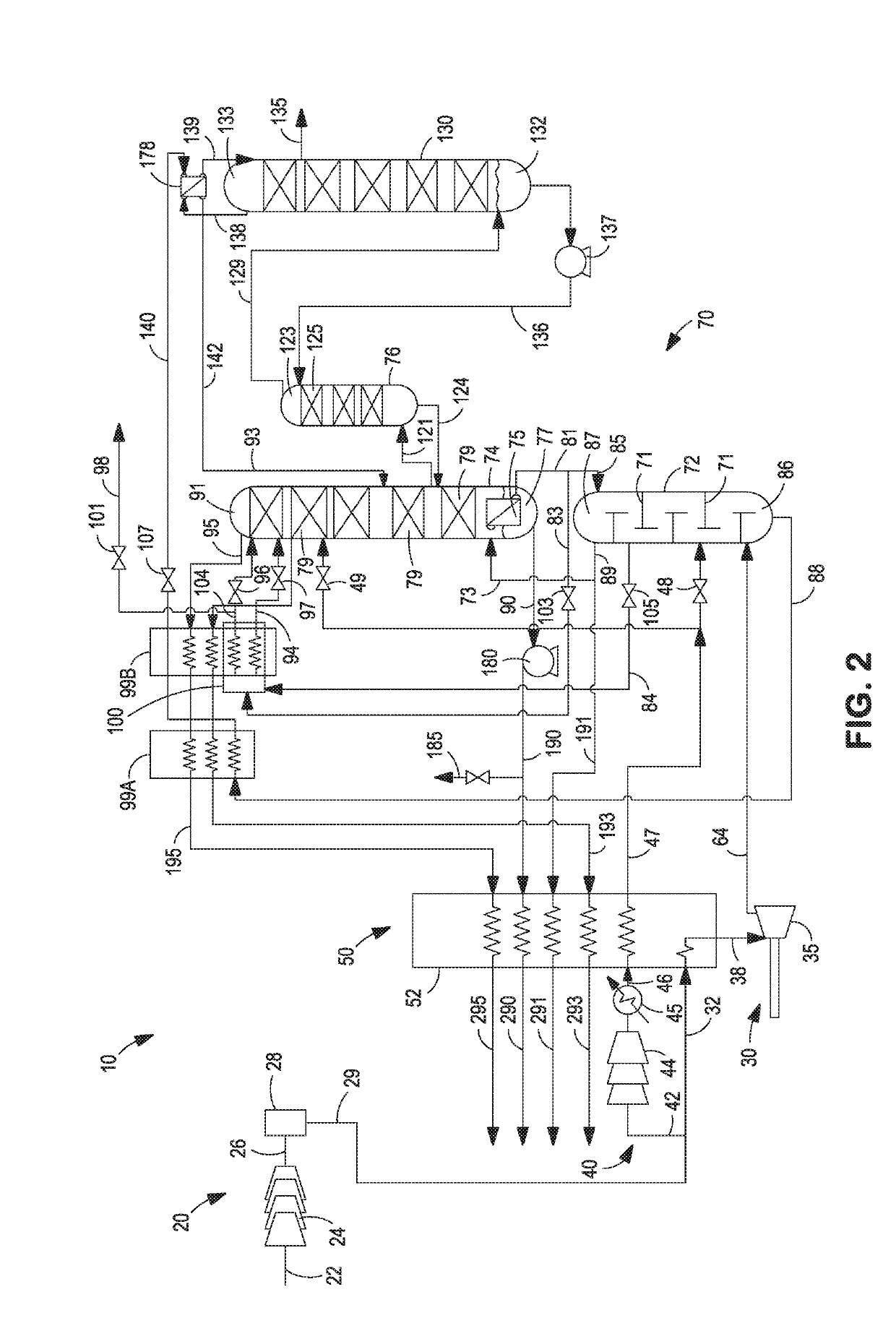
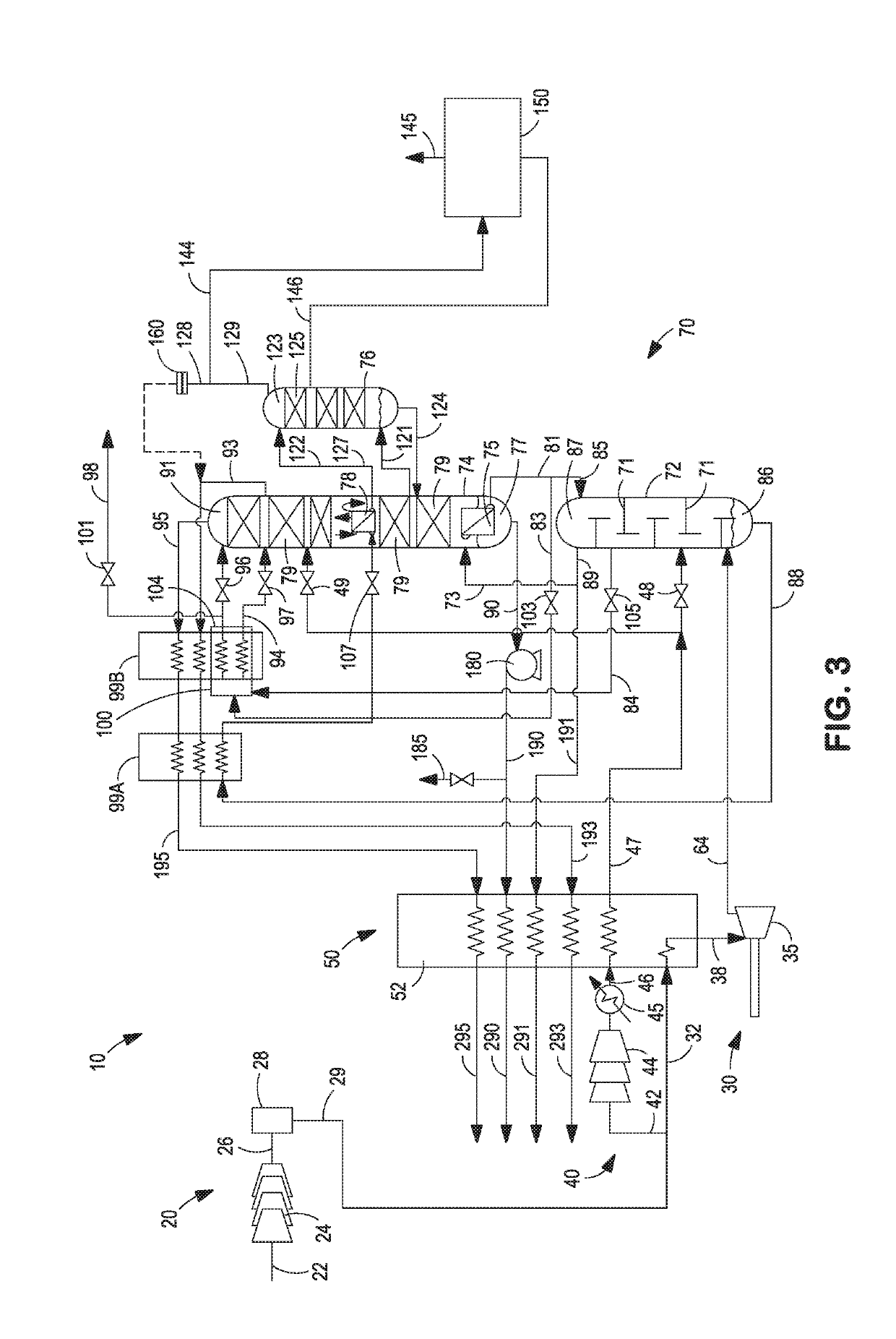
[0072]For various embodiments of the present system and method for flexible recovery of argon, a number of process simulations were run using various air separation unit operating models to characterize: (i) the impact of shifting between ‘low argon’ operating mode and ‘high argon’ operating mode on overall power consumption / savings and argon recovery in a large oxygen producing air separation unit;(ii) the impact of drawing shelf vapor on power consumption / savings and argon recovery in a large oxygen producing air separation unit; and (iii) the impact of using various splits of dirty shelf nitrogen and clean shelf nitrogen as the reflux stream to the lower pressure column on the power consumption / savings and argon recovery of a large oxygen producing air separation unit.

[0073]Table 1 shows the results of the computer based process simulation for the present systems and associated methods described above. For the process simulations, a 1300 ton per day (TPD) pumped liquid oxygen pla...


PUM


Abstract

A system and method for flexible production of argon from a cryogenic air separation unit is provided. The cryogenic air separation unit is capable of operating in a ‘no-argon’ or ‘low-argon’ mode when argon demand is low or non-existent and then switching to operating in a ‘high-argon’ mode when argon is needed. The recovery of the argon products from the air separation unit is adjusted by varying the percentages of dirty shelf nitrogen and clean shelf nitrogen in the reflux stream directed to the lower pressure column. The cryogenic air separation unit and associated method also provides an efficient argon production/rejection process that minimizes the power consumption when the cryogenic air separation unit is operating in a ‘no-argon’ or ‘low-argon’ mode yet maintains the capability to produce higher volumes of argon products at full design capacity to meet argon product demands.

Description

TECHNICAL FIELD[0001]The present invention relates to the recovery of products from a cryogenic air separation unit, and more particularly, to a system and method for the flexible recovery of argon from a cryogenic air separation unit. Still more particularly, the present invention relates to the flexible recovery of argon and other products from a cryogenic air separation unit through the use of clean shelf nitrogen and / or dirty shelf nitrogen as the reflux stream to the lower pressure column and varying the percentage of dirty shelf nitrogen in the total nitrogen reflux stream to achieve the desired product recovery and realize power saving efficiencies when operating in no argon recovery mode or low argon recovery mode.BACKGROUND[0002]Argon is a highly inert element used in the some high-temperature industrial processes, such as steel-making where ordinarily non-reactive substances become reactive. Argon is also used in various types of metal fabrication processes such as arc wel...

Claims


Application Information

Patent Timeline
IPC IPC(8): F25J3/04
CPCF25J3/04412F25J2205/60B01D2256/18B01D2257/102B01D2257/104F25J3/048F25J3/04884F25J3/04963F25J3/04969F25J3/0409F25J3/04175F25J3/04218F25J3/0423F25J3/04236F25J3/04296F25J3/04303F25J3/04678F25J3/04703F25J3/04721F25J3/04733F25J2200/94F25J2205/82F25J2245/42F25J2245/58F25J2250/02F25J2250/52F25J2250/58F25J2235/58
Inventor PROSSER, NEIL M.LUO, YANGLENZ, RICHARD D.SABODA, KEVIN J.
Owner PRAXAIR TECH INC
Why Eureka
Try Eureka