Imaging abnormality diagnosis device
a diagnostic device and abnormality technology, applied in the direction of image enhancement, process and machine control, instruments, etc., can solve the problems of local distortion of image, error in estimation of lane line or the like, image captured by in-vehicle camera area distorted,
- Summary
- Abstract
- Description
- Claims
- Application Information
AI Technical Summary
Benefits of technology
Problems solved by technology
Method used
Image
Examples
Embodiment Construction
[0018]Hereinafter, referring to the drawings, an imaging abnormality diagnosis device according to an embodiment will be described in detail. In the following description, the same reference numerals will be assigned to like elements.
[0019]Configuration of Vehicle
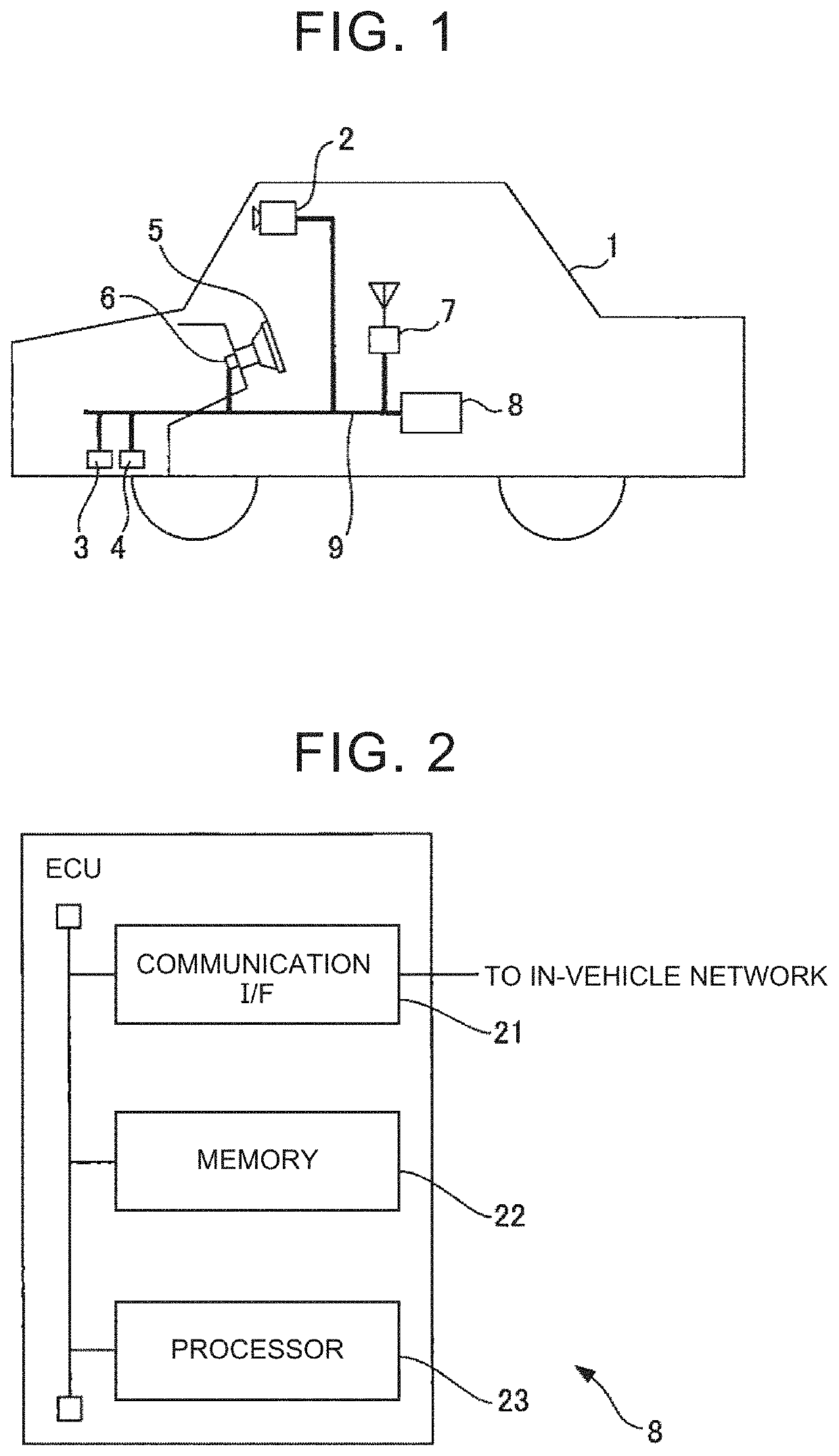
[0020]FIG. 1 is a diagram schematically illustrating the configuration of a vehicle on which an imaging abnormality diagnosis device according to this embodiment is mounted. As illustrated in FIG. 1, a vehicle 1 includes an in-vehicle camera 2, an acceleration sensor 3, a yaw rate sensor 4, a steering wheel 5, a steering angle sensor 6, a GPS receiver 7, and an electronic control unit (ECU) 8. The in-vehicle camera 2, the acceleration sensor 3, the yaw rate sensor 4, the steering wheel 5, the steering angle sensor 6, the GPS receiver 7, and the ECU 8 are communicably connected to each other via an in-vehicle network 9 conforming to a standard such as a controller area network (CAN).
[0021]The in-vehicle camera 2 images a pre...
PUM
 Abstract
Description
Claims
Application Information
 - R&D
- Intellectual Property
- Life Sciences
- Materials
- Tech Scout
- Unparalleled Data Quality
- Higher Quality Content
- 60% Fewer Hallucinations
Browse by: Latest US Patents, China's latest patents, Technical Efficacy Thesaurus, Application Domain, Technology Topic, Popular Technical Reports.
© 2025 PatSnap. All rights reserved.Legal|Privacy policy|Modern Slavery Act Transparency Statement|Sitemap|About US| Contact US: help@patsnap.com


