High efficiency compressed-air power generation system
a power generation system and high-efficiency technology, applied in the field of high-efficiency compressed-air power generation systems, can solve the problems of limiting heat transfer efficiency and limited power generation efficacy, and achieve the effect of improving heat transfer efficiency and power generation efficacy
- Summary
- Abstract
- Description
- Claims
- Application Information
AI Technical Summary
Benefits of technology
Problems solved by technology
Method used
Image

Examples
first embodiment
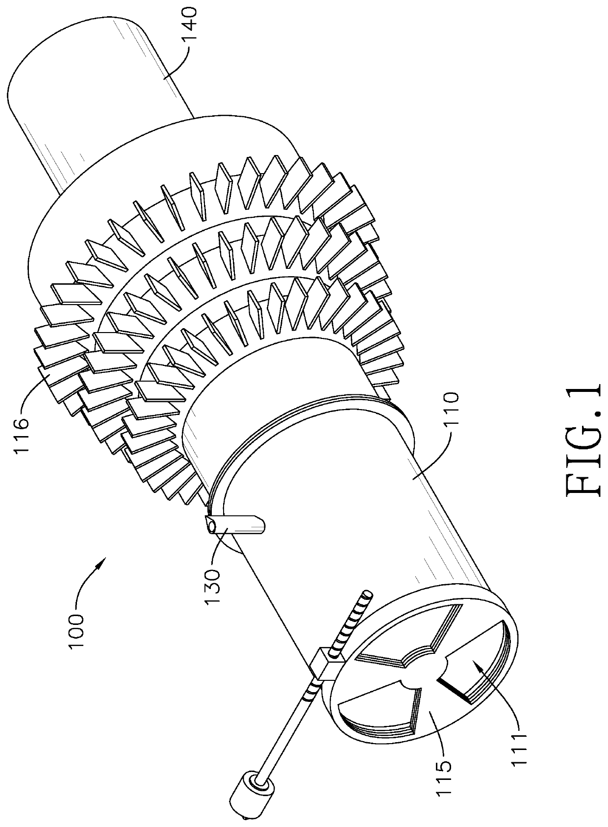
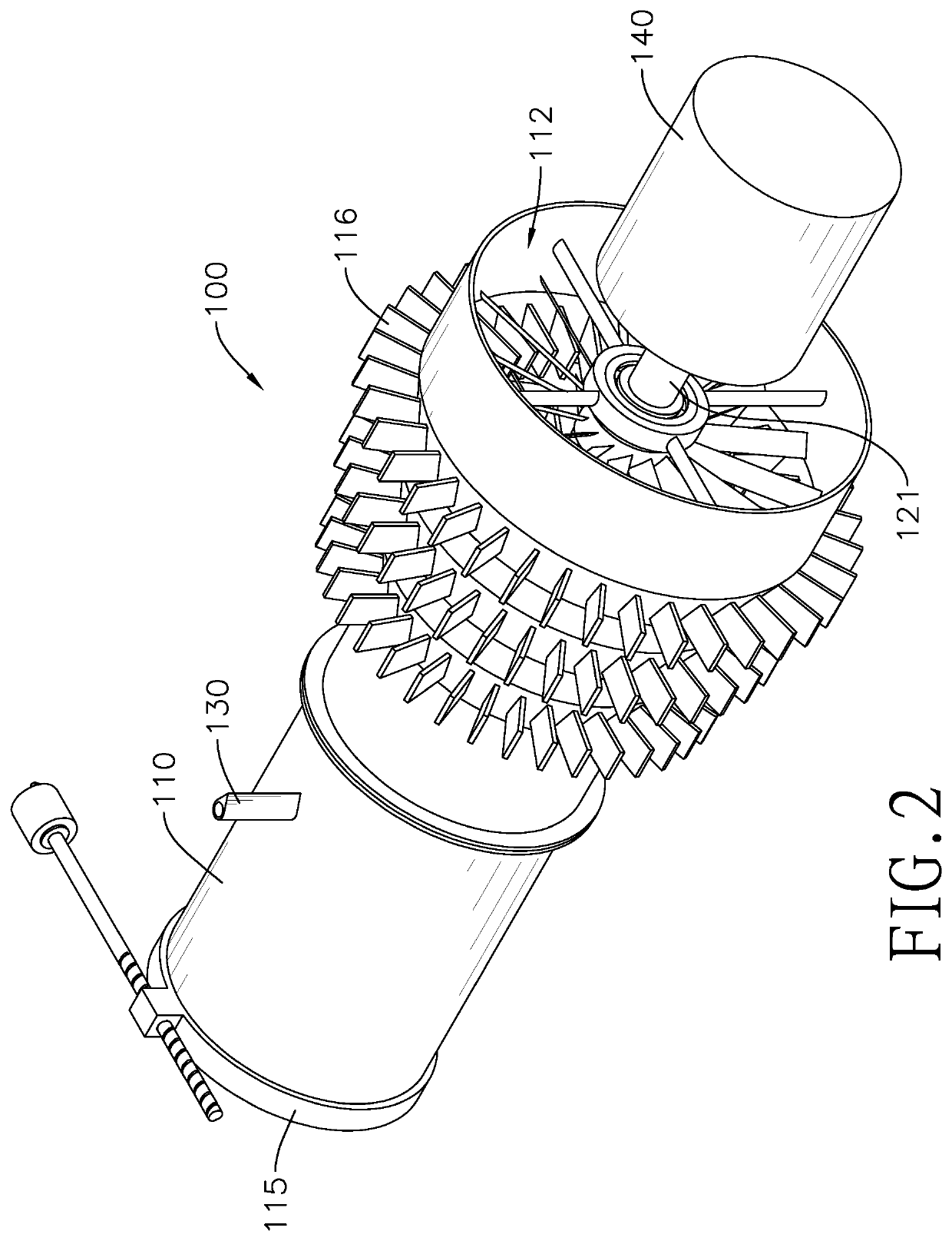
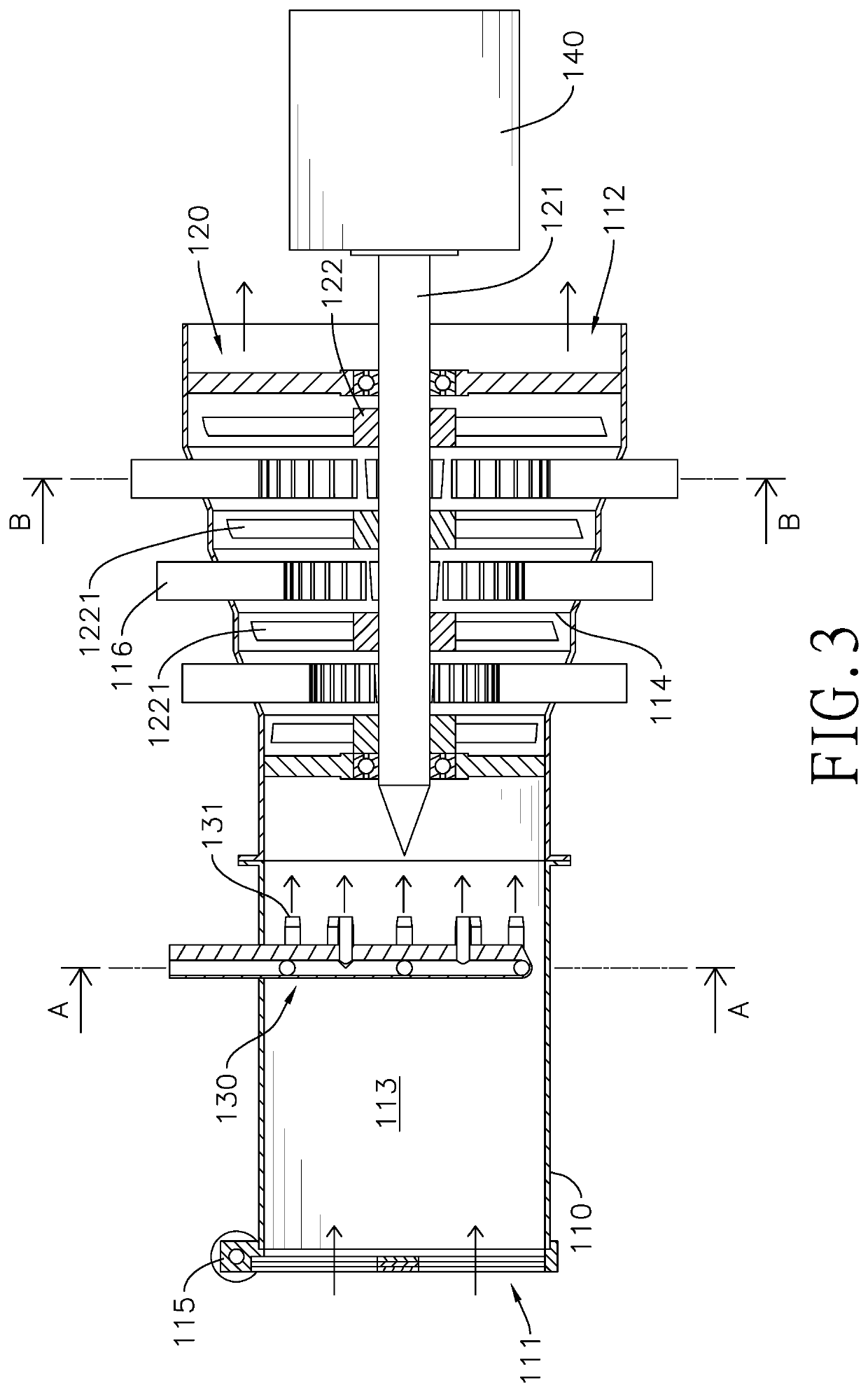
[0018]With reference to FIGS. 1 to 3, a high efficiency compressed-air power generation system in accordance with the present invention comprises a main generation unit 100 having a main casing 110, a main rotor 120, an air distributor 130, and a main generator 140. In the preferred embodiment, the main generation unit 100 further has a suction valve 115 and multiple heat exchanging fins 116.
[0019]The main casing 110 forms an elongated main passage, and the main passage has an intake section 113 and a turbine section 114. A cross section of the turbine section 114 of the main generation unit 100 preferably increases toward a direction away from the intake section 113. The main casing 110 has a suction opening 111 and a main outlet opening 112 each formed in a respective one of two opposite ends of the main casing 110. The suction opening 111 is connected to the intake section 113 of the main passage, and the main outlet opening 112 is connected to the turbine section 114 of the main...
second embodiment
[0028]With reference to FIG. 6, a high efficiency compressed-air power generation system in accordance with the present invention comprises a main generation unit 100A, an auxiliary generation unit 200A, and a back-feeding valve 300A.
[0029]The main generation unit 100A is substantially same as the main generation unit 100, but the main generation unit 100A further has a guiding tube 115A, an intake temperature sensor 151A, and an intake pressure sensor 152A. The intake temperature sensor 151A and the intake pressure sensor 152A are mounted in the intake section 113A of the main passage to measure temperature and pressure of the air flow in the intake section 113A.
[0030]The guiding tube 115A is disposed in the intake section 113A of the main passage. One of two ends of the guiding tube 115A protrudes from the intake section 113A to be in gaseous communication with the auxiliary generation unit 200A. The other end of the guiding tube 115A extends toward the main turbine wheels 122A of...
PUM
 Abstract
Description
Claims
Application Information
 - R&D Engineer
- R&D Manager
- IP Professional
- Industry Leading Data Capabilities
- Powerful AI technology
- Patent DNA Extraction
Browse by: Latest US Patents, China's latest patents, Technical Efficacy Thesaurus, Application Domain, Technology Topic.
© 2024 PatSnap. All rights reserved.Legal|Privacy policy|Modern Slavery Act Transparency Statement|Sitemap