Sealing sleeve for pipe offsets

a sealing sleeves and offset technology, applied in the direction of pipe joints, pipe elements, non-disconnectible pipe joints, etc., can solve the problems of sealing sleeves that are less suitable for being successfully used in offsets of pipes, packers cannot be vented and drawn out of sewage ducts, and leakage sealing in pipes from the interior of pipes

Active Publication Date: 2022-04-19
UHRIG KANALTECHN
View PDF24 Cites 0 Cited by
  • Summary
  • Abstract
  • Description
  • Claims
  • Application Information

AI Technical Summary

Benefits of technology

[0010]The object of the invention is to provide a sealing inner sleeve and a corresponding method by means of which a successful and satisfactory renovation of pipe offsets can be carried out.

Problems solved by technology

It is known to seal leaks in pipes from the interior of the pipe.
The sealing sleeves as known up to now are less suitable for being successfully used in offsets of pipes.
Due to the slow curing, the packer can only be vented and drawn out of the sewage duct after a few hours.
Another disadvantage is that the curing process takes several hours, causing long waiting periods.
Various pipe materials cannot be renovated by this method since their material does not bond with synthetic resin or does not form an adhesive connection with synthetic resin, respectively.
Finally, the inlet area of the glass fiber mat becomes frayed in the course of time, namely due to the sewage water flowing through, and in particular also due to the flushing surges for cleaning the pipes.
The resulting frayed fringe areas are a flow barrier and in some cases even facilitate a scouring of the glass fiber mat, ultimately resulting in leakages.
Among other things, the air cushion of the packer must be protected with regard to the stainless steel sleeve, since during the inflation of the air cushion this may be damaged by the bars located between the holes.
Finally, if pressure is exerted from the outside onto the damaged location, for instance if the renovated pipe offset is located below groundwater level, the sealing element may be pressed into the pipe interior through the holes in the stainless steel sleeve, since in this area no sufficient supportive effect is present by means of the stainless steel sleeve provided with holes.

Method used


Image

  • Sealing sleeve for pipe offsets
  • Sealing sleeve for pipe offsets
  • Sealing sleeve for pipe offsets

Examples


Embodiment Construction

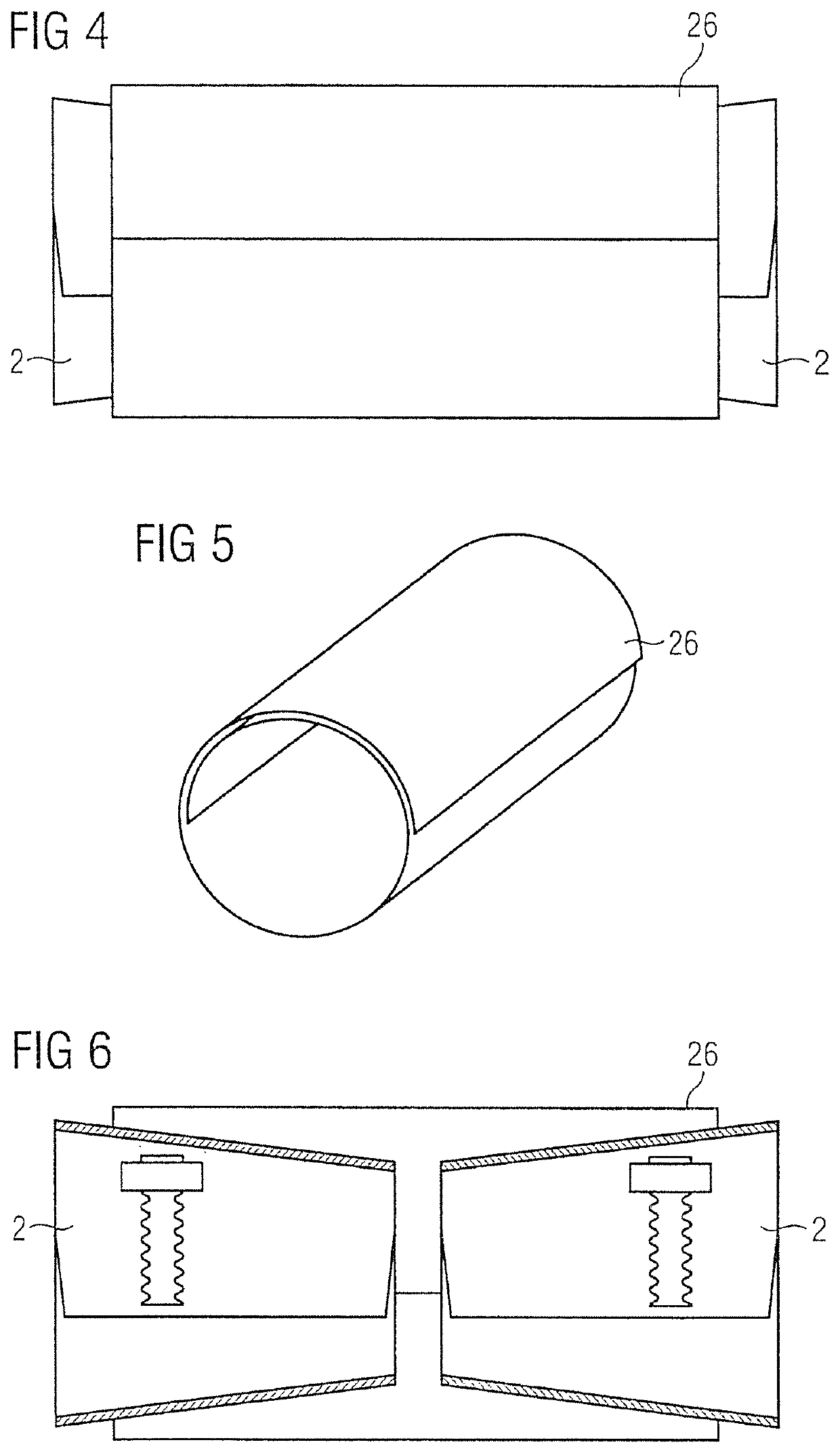
[0038]FIG. 1 shows a view onto the two sleeves 2, which are made of conically bent-round strips made of corrosion-resistant steel sheet, wherein the strip ends 4 of the two sleeves 2 overlap in circumferential direction. Thus, the sleeves 2 have the shape of a truncated cone or funnel, respectively.

[0039]FIG. 2 shows a side view onto the sleeve 2 in longitudinal axis direction, onto the larger opening 6 of sleeve 2. By means of the funnel-shaped or frustoconical design, respectively, of sleeve 2, in FIG. 2 also the rear, smaller opening 8 is shown. In the overlapping area 10 of sleeve 2 an arresting device 12 is shown. The arresting device 12 is again shown in more detail in subsequent FIG. 3, and allows for very small latching steps. To this aim, a slot 20 provided with two rows of teeth 16, 18 (FIG. 3) is arranged at the internal strip end 14. At the external strip end 22 a locking mechanism 24 which is not described in more detail is arranged, wherein the corresponding arresting ...


PUM


Abstract

A sealing inner sleeve for inserting into pipes, includes two frustoconical or substantially cylindrically bent-round sleeves formed of steel sheets, wherein the free ends of the steel sheets of the sleeves overlap in their circumferential directions and an arresting device is arranged in each of these overlapping regions and wherein the two sleeves are arranged at a distance from one another in a deformable jacket tube.

Description

BACKGROUND OF THE INVENTION[0001]The invention relates to a sealing inner sleeve for inserting into pipes.[0002]By using sealing inner sleeves, existing pipelines can be renovated, in particular, leaks in underground sewage water pipelines can be repaired without any excavation work.[0003]It is known to seal leaks in pipes from the interior of the pipe. To this end, sleeves are used which are bent together in an overlapped manner, have special sealing elements, are made of resilient, corrosion-resistant steel sheets and are inserted into the pipe to be sealed until the leak is reached. There, they are expanded by means of a pneumatically or hydraulically inflatable cushion or packer or by means of a mechanical mounting device, until they closely abut to the inner wall of the pipe as a result of the compression of the duroplastic sealing elements.[0004]An arresting device holds the sealing inner sleeve in the expanded position. In DE 195 44 877 C1 such an arresting device connected t...

Claims


Application Information

Patent Timeline
Patent Type & Authority Patents(United States)
IPC IPC(8): F16L25/14F16L13/14
CPCF16L25/14F16L13/147F16L25/12F16L55/163
Inventor BECHLER, CHRISTIAN
Owner UHRIG KANALTECHN
Why Eureka
Try Eureka