Method for connecting surface-mount electronic components to a circuit board

a technology of electronic components and circuit boards, applied in the field of manufacturing methods, can solve the problems of long time needed, limited reflow process, poor thermal and mechanical performance of solder pastes,

Active Publication Date: 2022-04-26
PULSEFORGE INC
View PDF12 Cites 0 Cited by
  • Summary
  • Abstract
  • Description
  • Claims
  • Application Information

AI Technical Summary

Problems solved by technology

However, there are some limitations to the reflow process.
For standard SAC-305 solder paste, the temperature is about 217° C. Another limitation of the reflow process is the lengthy time needed to process the solder paste to allow for the solder to reflow.
At present, such solder pastes tend to have poor thermal and mechanical performance as compared to standard SAC-compliant solder pastes.
With the reflow process, energy is transferred to electronic components, circuit board, and solder paste via convection, which presents another problem.
The shear from the air in the reflow oven may cause electronic components to blow off the circuit board or become misaligned before they are soldered to the circuit board.
This becomes a larger issue when the electronic components are very small as their aerodynamic cross-section to weight ratio is larger.
However, the laser process is inherently serial in nature, thus, the total amount of time needed for a circuit board having many solder joints will increase as the number of solder joints increases.
Furthermore, the laser process can suffer from beam non-uniformities that may cause electronic components to be unevenly heated.
This results in poor solder joints, damage to other parts of the circuit board, or “tombstoning” of electronic components.
One problem with this approach is that it takes a finite amount of time, approximately one second, to turn on or turn off the light source.
This limitation inhibits the ability of precisely controlling the power and energy profile that is deposited to the material being processed.
In the case when the target material is being conveyed, there is a similar problem in that the ideal exposure is generally linked to the conveyance rate.

Method used


Image

  • Method for connecting surface-mount electronic components to a circuit board
  • Method for connecting surface-mount electronic components to a circuit board
  • Method for connecting surface-mount electronic components to a circuit board

Examples


Embodiment Construction

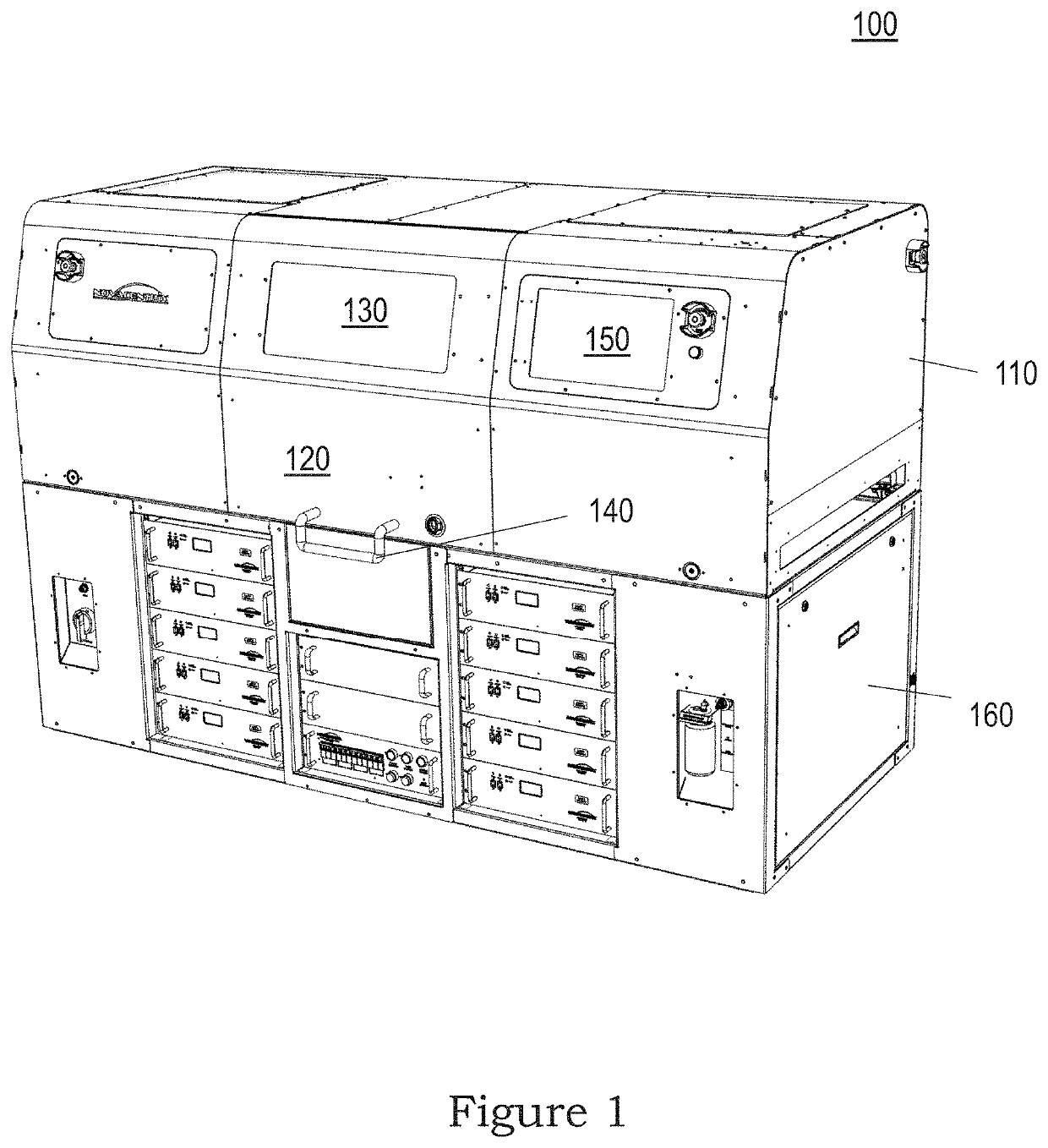
[0017]Referring now to the drawings and in particular to FIG. 1, there is depicted an isometric view of a system for thermally processing solder paste to connect electronic components to a circuit board, according to one embodiment. As shown, a system 100 includes an enclosure 110 resting on an equipment rack 160. Enclosure 110 includes a hatch door 120 that can be lifted open via a handle 140. A semi-transparent window 130 is provided in hatch door 120 to allow a user to observe any processing occurring within enclosure 110. At least one flashlamp (not shown) is positioned within enclosure 110 to enable thermal processing. Users can enter and receive information into and from system 100 via a touch-screen 150.

[0018]Enclosure 110 may include an environmentally controlled chamber (not shown) that can be filled with an inert gas, e.g., nitrogen, or a reactive gas, e.g., formic acid, or vacuum, in which thermal processing can be performed on electronic components. In addition, enclosur...


PUM

PropertyMeasurementUnit
temperatureaaaaaaaaaa
thicknessaaaaaaaaaa
temperatureaaaaaaaaaa

Abstract

A method for connecting an electronic component to a circuit board is disclosed. Initially, a substrate and an electronic component having solder located between them are placed under a flashlamp. Multiple light pulses from the flashlamp are applied to the electronic component, substrate and solder until the solder reflows. During the application of the light pulses, the power of one of the light pulses from the flashlamp and the temperature of the electronic component are measured, the measured power is converted to radiant exposure, and in response to the measured temperature of the electronic component, the duty cycle of a next light pulse is adjusted adaptively according to the radiant exposure of the one light pulse.

Description

TECHNICAL FIELD[0001]The present application relates to manufacturing methods in general, and, in particular, to a method for connecting surface-mount electronic components to a circuit board.BACKGROUND[0002]In general, electronic components can be connected to a circuit board via soldering. With the advent of surface mount technology and wave soldering, the need to solder electronic components manually onto a circuit board has been mostly eliminated from a production standpoint.[0003]Surface mount technology necessitates the usage of solder paste having solder particles dispersed in an organic flux. Solder paste is selectively deposited on a circuit board followed by the placement of electronic components to be soldered, and the circuit board is then placed in a reflow oven fitted with a conveyer. The reflow oven reflows solder paste by heating it to activate the flux in the solder paste to clean the surfaces and melt the solder. The molten solder wets the surfaces and solidifies, ...

Claims


Application Information

Patent Timeline
Patent Type & Authority Patents(United States)
IPC IPC(8): B23K1/00H05K3/34H05K13/04H05K13/08B23K1/005
CPCH05K3/3494B23K1/005H05K13/0465H05K13/0817H05K2203/0195H05K2203/10H05K2203/163B23K1/0016
Inventor GHOSH, RUDRESHPASSIAK, JOHN MICHAELATTAR, VAHID AKHAVANSCHRODER, KURT A.
Owner PULSEFORGE INC
Why Eureka
Try Eureka