
Striking or musical watch with an acoustic waveguide arrangement

a waveguide and musical watch technology, applied in the field of horology, can solve the problems of limiting the adaptation possibilities, affecting the quality of sound, so as to improve the quality and intensity of sound

Active Publication Date: 2022-05-03
MONTRES BREGUET
View PDF27 Cites 2 Cited by
  • Summary
  • Abstract
  • Description
  • Claims
  • Application Information

AI Technical Summary

Benefits of technology

The striking or musical watch described in this patent has a unique feature: it has a flexible waveguide that connects to the watch and guides the sound waves from a vibration source to a small loudspeaker on the watch. This allows the watch to produce high-quality, out-of-plane vibrations, which enhance the sound or melody perceived outside the watch. The perpendicular movement of the loudspeaker creates an improved listening experience compared to traditional watches.

Problems solved by technology

In the case of a watch, a vibration transmission element can consist of the plate, a casing ring, the case middle, a bezel gasket, for example, but these are not components optimized for the transmission of vibrations.
The configurations of these external parts are also dependent on the aesthetics of the watch and operating constraints, which may limit possibilities of adaptation.
However, the acoustic efficiency of all these arrangements is often insufficient, which constitutes a drawback.

Method used


Image

  • Striking or musical watch with an acoustic waveguide arrangement
  • Striking or musical watch with an acoustic waveguide arrangement

Examples


first embodiment

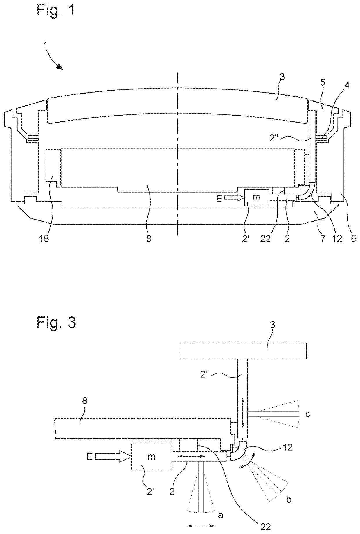
[0020]In the first embodiment shown in FIG. 1, at least partially flexible waveguide 2 is held on a rectilinear part on the side of its first portion 2′, which may be a first end of the guide, by flexible strips 22, for example, under the plate of watch movement 8. This rectilinear part on first portion 2′ may be rigid. The at least partially flexible waveguide 2 further comprises a curved part 12 for the change in direction of acoustic vibration and another rectilinear part 2″ connecting curved part 12 to radiating element 3, 4, 5. At least curved part 12 is on a flexible guide member. This other rectilinear part is also secured to the fixed part, for example to a fixed wall 18 above the plate by other flexible strips. The fixed wall may be a casing ring 18, but other connecting means can be provided.

[0021]The at least partially flexible waveguide 2 is in one piece with flexible strips 22, since any contact in the transmission of vibrations reduces the sound transmission quality.

[0...

second embodiment

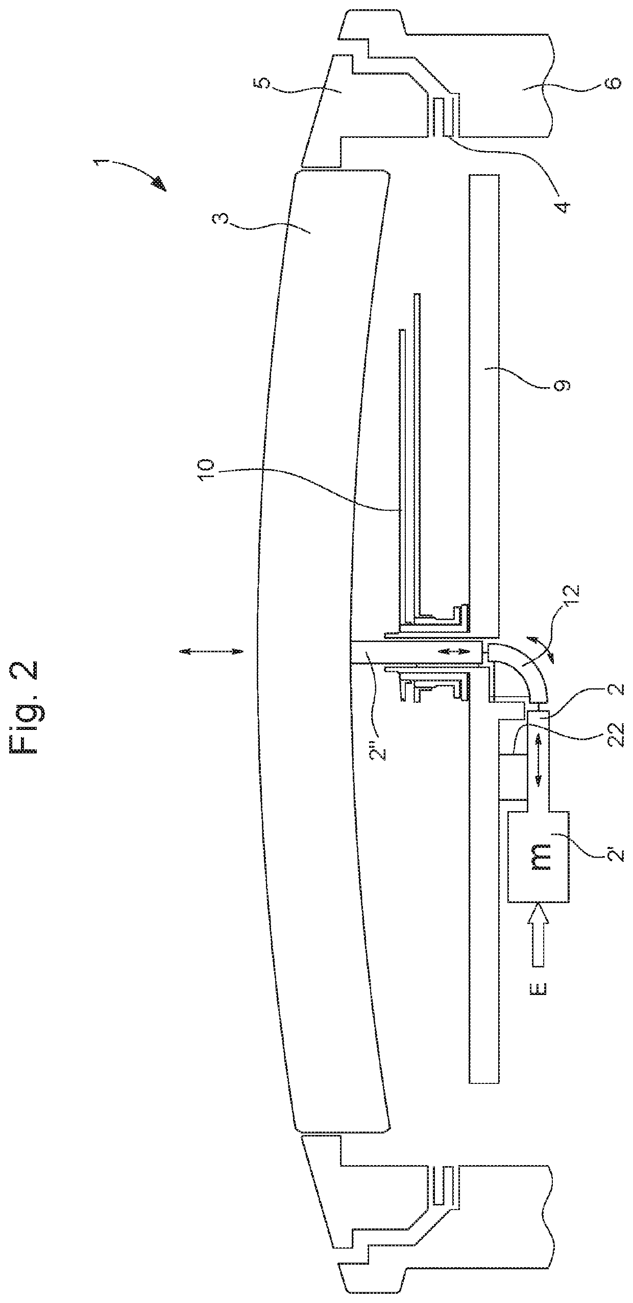
[0035]FIG. 2 schematically represents a cross-section of a striking or mechanical watch 1, which includes an arrangement for guiding acoustic waves inside the watch according to a For the sake of simplicity, the description of those elements presented and described with reference to FIG. 1 is not repeated.

[0036]The essential difference of this second embodiment compared to the first embodiment is that second portion 2″ of at least partially flexible waveguide 2 comes into contact with or strikes crystal 3 or is directly fixed to crystal 3 of the radiating element. Preferably, at least partially flexible waveguide 2 is connected to a fixed part, which, in this case, is watch dial 9 or the plate. First portion 2′ of at least partially flexible waveguide 2 is connected by flexible strips 22, for example metal strips, to an inner surface of dial 9. The curved or bent part 12 is in the centre of dial 9, for example at the centre of circular dial 9. The other rectilinear part with second...


PUM


Abstract

A striking or musical watch with an acoustic waveguide arrangement. The striking or musical watch (1) includes an at least partially flexible waveguide (2) secured to a fixed part (8) inside the watch to guide the acoustic waves generated by a first portion (2′) of the at least partially flexible waveguide towards a radiating element. The radiating element can include a watch crystal (3) connected to a bezel (5) and a membrane (4) for connecting the bezel to a middle part (6) of a watch case. The flexible waveguide is configured to change the direction of acoustic vibration from the first portion to the radiating element.

Description

CROSS-REFERENCE TO RELATED APPLICATIONS[0001]This application claims priority to European Patent Application No. 19157246.0, filed Feb. 14, 2019, the entire contents of which are incorporated herein by reference.FIELD OF THE INVENTION[0002]The invention concerns a striking or musical watch comprising an acoustic waveguide arrangement.BACKGROUND OF THE INVENTION[0003]In the field of horology, a watch can be provided with a striking mechanism for indicating minute repeaters or for producing music at predefined moments. In the case of a striking mechanism using gongs, the metal gong or gongs used are generally circular in shape and placed in a plane parallel to the watch dial. One end or several ends of each gong are secured to at least one gong-carrier integral with the main plate of the watch movement or with the watch case middle. The other end of each gong can generally move freely. The vibration of each gong is produced by the impact of a corresponding hammer on the gong in proxim...

Claims


Application Information

Patent Timeline
Patent Type & Authority Patents(United States)
IPC IPC(8): G04B21/08G04B23/02G04B37/00
CPCG04B21/08G04B23/028G04B37/0075G04B37/088G04B37/087G04B23/12G04C21/02G04B21/02G04C21/34G10K9/10
Inventor STRANCZL, MARC
Owner MONTRES BREGUET
Learn More