Electrical machine for driving propulsion

a technology of electric motors and propulsion motors, applied in the direction of propulsion by batteries/cells, electric devices, transportation and packaging, etc., can solve the problems of affecting the operation of the electric machine, the failure of the stator winding system of the machine, and the breakdown of the electrical machine, so as to reduce the power, suppress the induction of undeired current in the faulty winding system, and the effect of effective use of the redundancy of the electrical machin

Active Publication Date: 2022-05-10
ROLLS ROYCE DEUT LTD & CO KG
View PDF10 Cites 0 Cited by
  • Summary
  • Abstract
  • Description
  • Claims
  • Application Information

AI Technical Summary

Benefits of technology

[0013]On account of the partial rotors or the stator winding systems each being arranged one behind the other in the axial direction, it is possible to prevent currents being induced in the stator winding system of the faulty partial drive system by the still rotating partial rotor of the intact partial drive system in the event of a fault. This is not possible in the case of stator winding systems that are arranged one behind the other or next to one another or alternately in the circumferential direction.
[0014]In each case one of the components of a group of components including one of the stator winding systems and the partial rotor that is associated with the stator winding system is arranged radially within the other component of the group of components. In a first variant, the partial rotors are configured as internal rotors. Each of the partial rotors is arranged radially within the respectively associated stator winding system. In a second variant, the partial rotors are configured as external rotors. Each of the partial rotors is arranged radially outside the respectively associated stator winding system. The two variants provide a reduced physical size of the electrical machine as seen in the axial direction.
[0015]In an embodiment, the stator winding systems are DC-isolated from one another. As an alternative, provision may be made for the stator winding systems to be electrically connected to one another during normal operation, but for it to be possible, for example in the event of a fault, to DC-isolate the stator winding systems. The measure of permanent isolation or DC-isolation, that is to be established, of the stator winding systems also has the effect that no significant currents flow in the stator winding system of the faulty partial drive system in the event of a fault.
[0030]The use of the freewheeling devices includes the effect that each of the electric motors may be mechanically uncoupled from the common shaft, so that firstly, on account of the freewheeling devices, none of the partial rotors may transmit a working torque to the common motor shaft in the direction of rotation counter to the working direction of rotation. Secondly, the shaft, that always rotates in the same working direction of rotation, cannot apply any torque to the respectively uncoupled partial rotors on account of the freewheeling devices. Therefore, if on account of a fault and corresponding disconnection of the associated stator winding system, for example, one of the partial rotors is no longer driven by the associated stator winding system, the partial rotor will come to a standstill since the still rotating shaft cannot transmit any torque to the partial rotor owing to the use of the freewheeling devices. Consequently, when the partial rotor is at a standstill, no current may be induced in the disconnected stator winding system by the partial rotor, as a result of which the risk of overheating and fire described in the introductory part may be substantially precluded.
[0031]If a fault, for example an excessive temperature or an insulation fault, is detected in one of the stator winding systems by the drive controller or if one of the voltage sources breaks down, the respectively involved voltage source or voltage source in question is DC-isolated. The intact partial drive system including the stator winding system and the associated partial rotor may continue to operate alone, so that the electrical machine continues to remain functional with a correspondingly reduced power. By the freewheeling device of that partial rotor that interacts with the faulty winding system, the rotation of the partial rotor is prevented owing to a lack of interlocking or force-fitting connection with the motor shaft, so that induction of undesired current in the faulty winding system is also suppressed. After deactivation, including DC-isolation, of the associated current source, no more energy may be introduced into the faulty winding system as a result. No more current flows across the damaged point of the winding system that would cause a further introduction of thermal energy and therefore could constitute a fire hazard in the further course.
[0032]Accordingly, the presented solution allows for effective use of the redundancy of the electrical machine including a plurality of stator winding systems that are DC-isolated from one another by preventing the undesired introduction of energy into a damaged winding system by decoupling the associated rotor part with a freewheeling device, this leading to a reduction in the probability of occurrence of a fire in the electrical machine.

Problems solved by technology

In electrical machines, the insulations of the stator winding system of the machine may fail on account of material or production faults that are not identified or may not be identified and also in the case of operational overloads, such as due to voltage and / or current peaks for example.
A failure causes a functional breakdown in the further course of damage and, in the worst-case scenario, a fire in the electrical machine.
A development of this type constitutes, in principle, a risk situation since at least a breakdown and possibly damage to the machine occurs, and may have more or less serious consequences depending on the application of the machine.
For example, in the case of application of the electrical machine as part of the drive system of an electrically or hybrid-electrically driven aircraft, the breakdown of the electrical machine may have fatal consequences.
Although the described system allows operation to continue, the system is not configured to prevent an electric current from continuing to flow through the faulty winding system in the event of a fault, and may lead to overheating of the machine.
Consequently, this may and has to be immediately switched off when a fault is established.

Method used


Image

  • Electrical machine for driving propulsion

Examples


Embodiment Construction

[0034]Terms such as “axial” and “radial” relate to the shaft or axis used in the respective FIGURE or in the respectively described example. The directions axial and radial always relate to a rotation axis of the respective rotor.

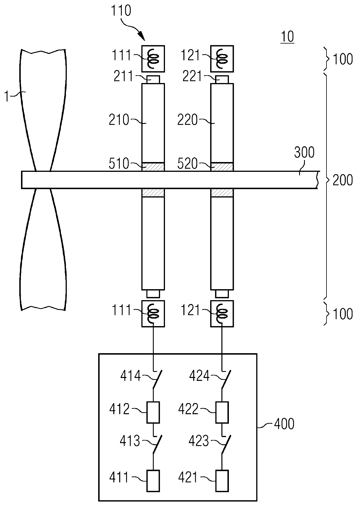
[0035]FIG. 1 depicts, by way of example and in simplified form, an electrical machine 10 that is configured as an electric motor or drive arrangement. Various components of the machine may be arranged differently depending on the configuration of the electrical machine as a generator or as an electric motor and / or as, for example, a radial or axial flux machine with a rotor that is configured as an internal or else as an external rotor, etc.

[0036]The electric motor 10 may be provided, for example, in order to drive a propulsion 1 of an aircraft (not illustrated), for example a propeller 1, in such a way that the propeller 1 rotates in a working direction of rotation in order to propel the aircraft. Other uses of the electrical machine for drive purposes or ...


PUM


Abstract

The invention relates to a particularly redundant electrical machine (10) for driving a means of propulsion (1) with increased reliability. The machine (10) comprises a plurality of independent partial rotors (210, 220) which are respectively coupled to a common shaft (200) by means of freewheel devices (510, 520) in order to drive said shaft and the means of propulsion (1) therewith in a working direction of rotation. The machine (10) also comprises a plurality of independent stator winding systems (111, 121), a stator winding system (111, 121) and a partial rotor (210, 220) being respectively associated with each other and arranged in such a way that they can electromagnetically interact with each other. The stator winding systems (111, 121) are successively arranged in the axial direction. Similarly, the partial rotors (210, 220) are successively arranged in the axial direction.

Description

CROSS REFERENCE TO RELATED APPLICATIONS[0001]This present patent document is a § 371 nationalization of PCT Application Serial Number PCT / EP2017 / 076946, filed Oct. 23, 2017, designating the United States, which is hereby incorporated in its entirety by reference. This patent document also claims the benefit of DE 102016221304.0, filed on Oct. 28, 2016, which is also hereby incorporated in its entirety by reference.FIELD[0002]Embodiments relate to an electrical machine for driving propulsion with increased reliability.BACKGROUND[0003]In electrical machines, the insulations of the stator winding system of the machine may fail on account of material or production faults that are not identified or may not be identified and also in the case of operational overloads, such as due to voltage and / or current peaks for example. Faults may occur, for example, when a turns short, a winding short or a short to ground occurs in the stator winding system. A failure causes a functional breakdown in ...

Claims


Application Information

Patent Timeline
Patent Type & Authority Patents(United States)
IPC IPC(8): H02K3/50B60L3/00
CPCB60L3/0061B60L3/0069H02K3/505B60L2200/10B60L2220/42B60L2240/425H02K2213/06B60L3/0046B60L3/0092B60L3/04H02K7/116H02K7/14H02K16/00B60L2220/50B60L50/51Y02T10/70
Inventor WOLLENBERG, JOHANNES
Owner ROLLS ROYCE DEUT LTD & CO KG
Why Eureka
Try Eureka