
Fluid pump

a technology of fluid pump and retainer, which is applied in the direction of machines/engines, liquid fuel engines, and positive displacement liquid engines. it can solve the problems of increasing the number of assembly processes, and the weight of the entire pump, so as to reduce the manufacturing cost, easy assembly, and easy maintenance.

Active Publication Date: 2022-05-10
LUXROBO CORP
View PDF21 Cites 0 Cited by
  • Summary
  • Abstract
  • Description
  • Claims
  • Application Information

AI Technical Summary

Benefits of technology

The present invention aims to provide a small and light fluid pump that can be used in various fields such as toys and small robots. The invention achieves this by giving a sealing function to an elastic member coupled to a piston to prevent leakage of working fluid. Additionally, there is no retainer and no piston shoe, which reduces the size and weight of the pump.

Problems solved by technology

However, there is a problem that the number of the parts of the entire pump, the number of assembly processes, and the weight of the entire pump are increased by the retainer and the piston shoe.
In particular, the retainer and the piston shoe need to be assembled, the piston and the piston shoe need to be assembled, and precise work is required for the assembling, so automation is difficult, and accordingly, there is a problem that the manufacturing cost is further increased.
Further, the piston shoe needs to be fitted to the retainer, and to this end, any one of them should be made of an elastic material or it is required to divide the retainer into several parts and fit the piston shoe therebetween, which makes it more difficult to manufacture the pump.
A large load is applied to the joint between the retainer and the piston shoe when the piston is pulled from the cylinder toward the swash plate, so, in this process, there is a problem that the retainer and the piston shoe may be worn, or torn, if severe, and the efficiency of the pump decreases due to excessive separation force.
Further, working fluid leaks through the gap between the piston and the cylinder in some time in the hydraulic pumps of the related art, so it is required to install a separate sealing member between the piston and the cylinder in order to prevent the leakage.
Installing a sealing member for every piston not only increases the number of parts, but also makes it difficult to downsize a pump.

Method used


Image

  • Fluid pump
  • Fluid pump
  • Fluid pump

Examples


Embodiment Construction

[0038]Hereinafter, some embodiments of the present invention are described in detail with exemplary drawings. It should be noted that when components are given reference numerals in the drawings, the same components are given the same reference numerals even if they are shown in different drawings. In the following description of embodiments of the present invention, when detailed description of well-known configurations or functions is determined as interfering with understanding of the embodiments of the present invention, they are not described in detail.

[0039]Terms “first”, “second”, “A”, “B”, “(a)”, and “(b)” can be used in the following description of the components of embodiments of the present invention. The terms are provided only for discriminating components from other components and, the essence, sequence, or order of the components are not limited by the terms. When a component is described as being “connected”, “combined”, or “coupled” with another component, it should...


PUM


Abstract

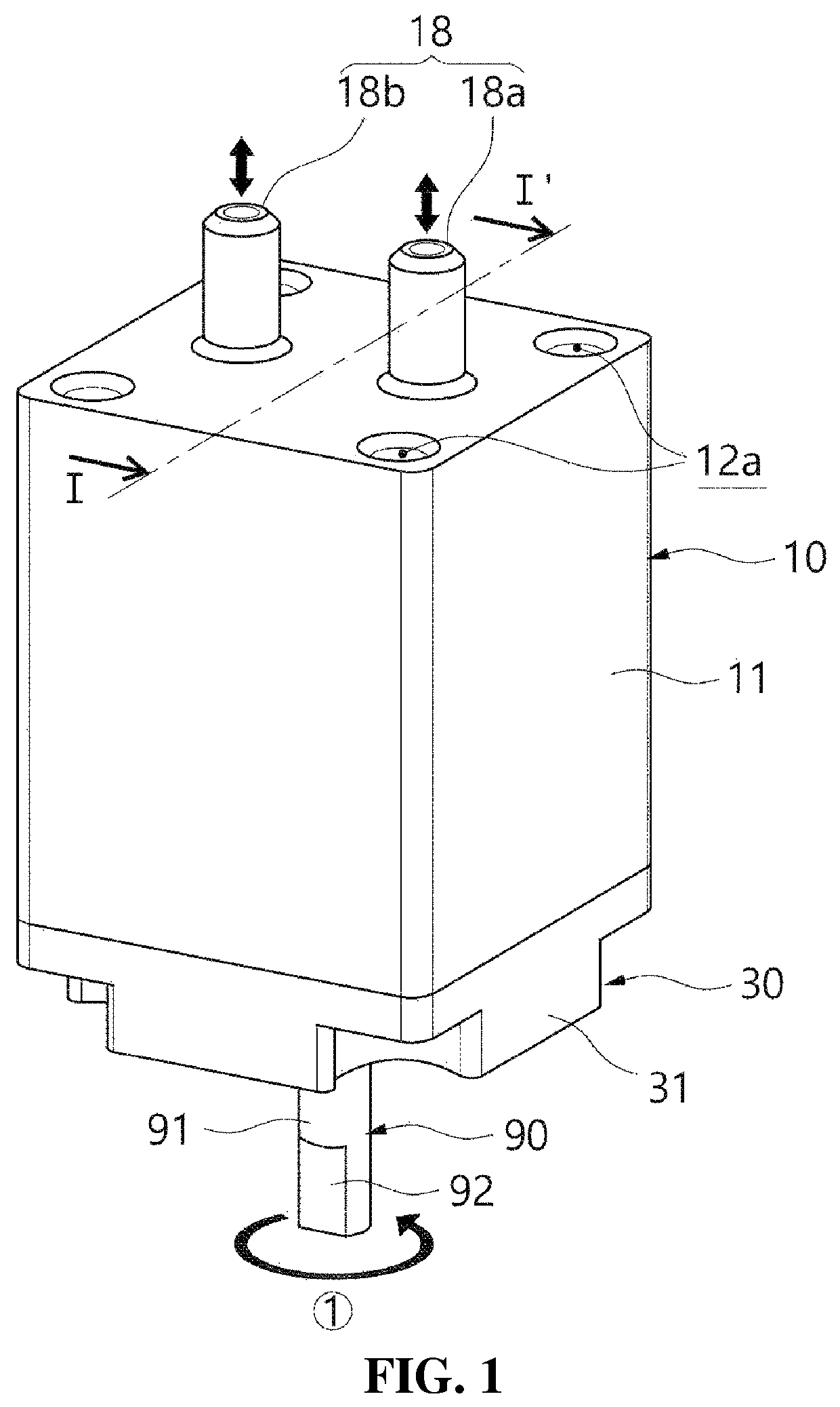
A fluid pump is proposed. The fluid pump includes: a housing having an operation space and having connection ports disposed at a side in the operation space to discharge working fluid and suctioning working fluid from the outside; a swash plate coupled to the housing at an opposite side to the connection ports and having an inclined surface on a top facing the operation space; a cylinder block disposed in the operation space to be rotated by a driving shaft and having several cylinder rooms therein that extend in parallel with the driving shaft.

Description

CROSS REFERENCE TO RELATED APPLICATION[0001]The present application claims priority to Korean Patent Application No. 10-2019-0070882, filed Jun. 14, 2019, the entire contents of which is incorporated herein for all purposes by this reference.BACKGROUND OF THE INVENTIONField of the Invention[0002]The present invention relates to a fluid pump and, more particularly, to a fluid pump without a retainer connecting a swash plate and a piston to each other.Description of the Related Art[0003]A common fluid pump, for example, a hydraulic pump uses the phenomenon in which the phase changes when a swash plate having an inclined surface is rotated. According to the brief structure, a piston that generates hydraulic pressure by moving straight in a cylinder is connected to a retainer through a piston shoe. The retainer, which retains the piston shoe, is in contact with the swash plate, so the piston can be in close contact with the swash plate. In this configuration, the retainer is connected t...

Claims


Application Information

Patent Timeline
Patent Type & Authority Patents(United States)
IPC IPC(8): F04B1/124F04B45/02F04B1/2014
CPCF04B45/022F04B1/124F04B1/2014F04B1/14F04B1/146F04B1/122F04B53/14F05B2210/11
Inventor LEE, YONG KWUNKIM, YOUNG SOO
Owner LUXROBO CORP
Learn More