Power generating element

a power generation element and power generation technology, applied in the direction of generator/motor, electrical apparatus, electric/electrostriction/magnetostriction machine, etc., can solve the problems of low power generation efficiency and physical limitations, and achieve the effect of increasing power generation capacity, simple structure, and increasing overall resonan

Active Publication Date: 2022-05-10
TRI FORCE MANAGEMENT CORP
View PDF35 Cites 2 Cited by
  • Summary
  • Abstract
  • Description
  • Claims
  • Application Information

AI Technical Summary

Benefits of technology

[0017]The power generating element according to the invention includes at least two mutually connected resonance systems, and is configured so that the frequency bands of the half-value widths of the resonance characteristics overlap each other. As such, the Q of the overall resonance can be greatly increased due to the interaction between the resonance systems. Accordingly, it is possible to dramatically increase power generation capacity over that of conventional levels for vibration in frequency bands in which half-value widths overlap each other. Moreover, a simple structure is achieved, which enables simple manufacturing using common manufacturing processes.

Problems solved by technology

With the conventional power generating element 18 described above and the piezoelectric power generating device described in Patent Document 1, it is possible to increase power generation capacity by increasing the Q factor of the resonance system, but there are physical limitations thereto.
Consequently, power generation efficiency has been low even in cases where the resonance frequency frz has been precisely matched to the frequency fz of the applied vibration.

Method used


Image

  • Power generating element
  • Power generating element
  • Power generating element

Examples


first embodiment

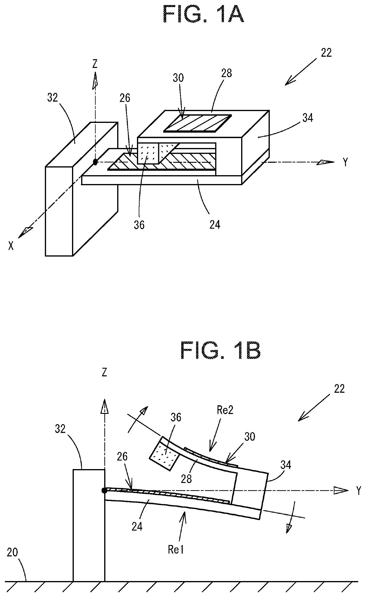
[0052]Next, the power generating element of the invention will be described while referencing FIGS. 1A to 2B. As illustrated in FIG. 1A, a power generating element 22 according to this embodiment includes a first plate-like structure 24 having flexibility, a first piezoelectric element 26 that generates a charge on the basis of a deflection of the first plate-like structure 24, a second plate-like structure 28 having flexibility, a second piezoelectric element 30 that generates a charge on the basis of a deflection of the second plate-like structure 28, and a pedestal 32 that supports the first plate-like structure 24 as a cantilevered structure. The power generating element 22 is used by attaching the pedestal 14 to a vibration source 20. In an XYZ three-dimensional coordinate system, the plate surfaces of the plate-like structures 24 and 28 are disposed so as to be surfaces parallel to the XY plane.

[0053]A base end portion of the first plate-like structure 24 is directly connected...

second embodiment

[0078]Next, the power generating element of the invention will be described while referencing FIGS. 6A to 8B. As illustrated in FIG. 6A, a power generating element 50 according to this embodiment includes a first plate-like structure 52 having flexibility, a first piezoelectric element 54 that generates a charge on the basis of a deflection of the first plate-like structure 52, a second plate-like structure 56 having flexibility, a second piezoelectric element 58 that generates a charge on the basis of a deflection of the second plate-like structure 56, a third plate-like structure 60 having flexibility, and a third piezoelectric element 62 that generates a charge on the basis of a deflection of the third plate-like structure 60. The power generating element 50 also includes a pedestal 64 that supports the first plate-like structure 52 as a cantilevered structure. The power generating element 50 is used by attaching the pedestal 64 to a vibration source 20. In an XYZ three-dimension...

third embodiment

[0094]Next, the power generating element of the invention will be described while referencing FIGS. 10A to 10C. A power generating element 78 according to this embodiment includes a first plate-like structure 80 having flexibility, a first piezoelectric element 82 that generates a charge on the basis of a deflection of the first plate-like structure 80, a second plate-like structure 84 having flexibility, a second piezoelectric element 86 that generates a charge on the basis of a deflection of the second plate-like structure 84, and a pedestal 88 that supports the first plate-like structure 80 as a cantilevered structure. The power generating element 78 is used by attaching the pedestal 88 to a vibration source 20. In an XYZ three-dimensional coordinate system, the plate surfaces of the plate-like structures 80 and 84 are disposed on planes parallel to the XY plane. It is preferable that the planes parallel to the XY plane are the same plane.

[0095]The pedestal 88 has a rectangular t...


PUM


Abstract

A power generating element is provided that includes first and second plate-like structures, a pedestal that supports the first plate-like structure, and first and second piezoelectric elements that generate charges on the basis of the deflections of the two plate-like structures. A base end portion of the first plate-like structure is connected to the pedestal, and a direction from the base end portion toward the tip end portion of the first plate-like structure is a Y-axis positive direction. A base end portion of the second plate-like structure is connected to the tip end portion of the first plate-like structure via a connection body, and a direction from the base end portion toward the tip end portion of the second plate-like structure is a Y-axis negative direction. A frequency band of a half-value width of a resonance system formed on the basis of the flexibility of the second plate-like structure at least partially overlaps a frequency band of a half-value width of a resonance system formed on the basis of the flexibility of the first plate-like structure.

Description

BACKGROUND OF THE INVENTIONField of the Invention[0001]The present invention relates to a power generating element that generates power by converting mechanical vibration energy into electric energy.Background Art[0002]A power generating element 18 is described in the related art. As illustrated in FIG. 14A, this power generating element 18 includes a flexible plate-like structure 10, a piezoelectric element 12, a pedestal 14, and a weight 16 disposed on a tip portion of the plate-like structure 10. The piezoelectric element 12 generates a charge on the basis of a deflection of the plate-like structure 10. The pedestal 14 supports a base end portion of the plate-like structure 10 as a cantilevered structure. The power generating element 18 is used by attaching the pedestal 14 to a vibration source 20. In a Cartesian coordinate system, that is, an XYZ three-dimensional coordinate system, the plate-like structure 10 is disposed such that the plate surface thereof becomes a surface par...

Claims


Application Information

Patent Timeline
Patent Type & Authority Patents(United States)
IPC IPC(8): H02N2/18
CPCH02N2/188H02N2/186H10N30/30
Inventor OKADA, KAZUHIROOKADA, MIHO
Owner TRI FORCE MANAGEMENT CORP
Why Eureka
Try Eureka