Supercharge Your Innovation With Domain-Expert AI Agents!

Wafer storage container

a storage container and wafer technology, applied in the direction of basic electric elements, semiconductor/solid-state device manufacturing, electrical equipment, etc., can solve the problems of affecting the reliability of the wafer, and affecting the efficiency so as to prevent the inefficient humidity control of the storage chamber, prevent the contamination of the wafer, and ensure the compatibility of the wafer storage container

Active Publication Date: 2022-06-07
WOO BUM JE
View PDF20 Cites 0 Cited by
  • Summary
  • Abstract
  • Description
  • Claims
  • Application Information

AI Technical Summary

Benefits of technology

Ensures quick and efficient control of purge gas flow, preventing contamination and oxidation, and maintaining optimal humidity levels within the storage chamber.

Problems solved by technology

As a result, the residual substances may consequently contaminate semiconductor manufacturing equipment during the processes and etch pattern defects, etc. may occur, resulting in degrading reliability of the wafers.
However, the wafer carrier of Patent Document 1 described above is problematic in that in a case where exhaust of the air discharge part is blocked by closing the air discharge valve, the contaminants may remain in the internal storage space.
As such, when the contaminants flow into the internal storage space, contamination of the wafer may occur, and humidity control of the internal storage space may not be efficiently performed, causing oxidation of the wafer.
In particular, in a case where the gas supply line between the injection port and the gas supply valve has a long length, too much inert gas is unintentionally supplied into the wafer carrier.
Thus, when a user desires to quickly block the supplying of the inert gas, this may not be achieved.

Method used


Image

  • Wafer storage container
  • Wafer storage container
  • Wafer storage container

Examples


Embodiment Construction

[0044]The term ‘purge gas’ referred to below refers generally to an inert gas for removing fumes on a wafer. In particular, it may be a nitrogen (N2) gas which is used as the inert gas.

[0045]In addition, the term ‘purging’ refers generally to a method of preventing oxidation of the wafer by eliminating the fumes that remain on the surface of the wafer through injection of a purge gas onto the wafer, or by eliminating moisture in a storage chamber.

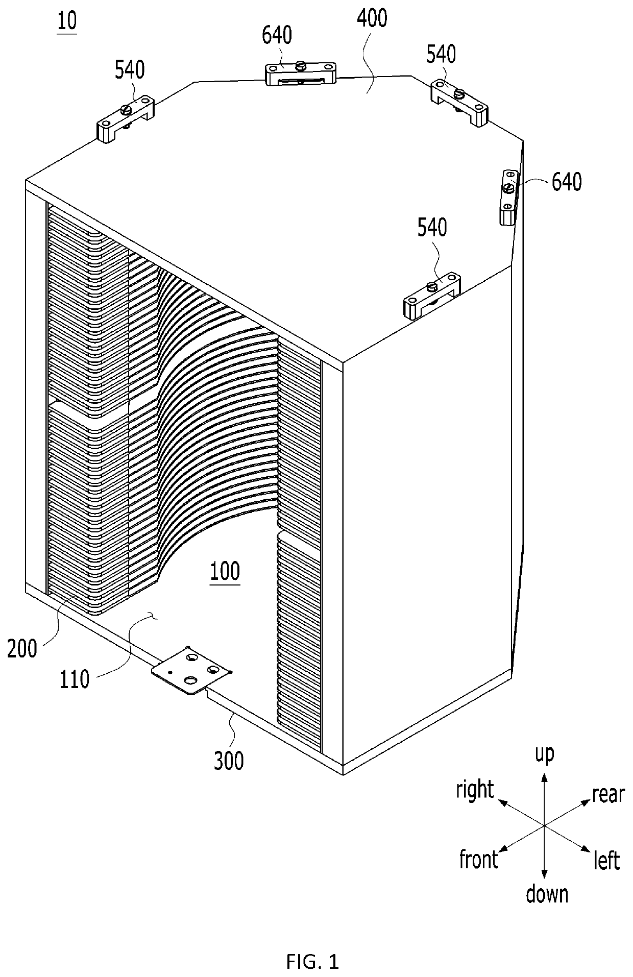
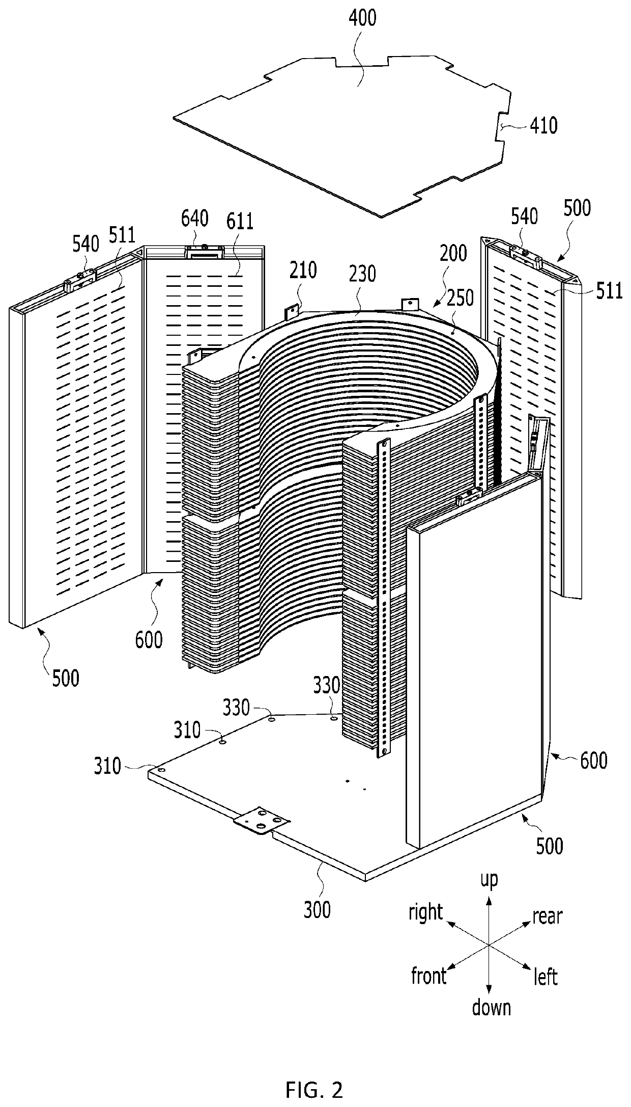
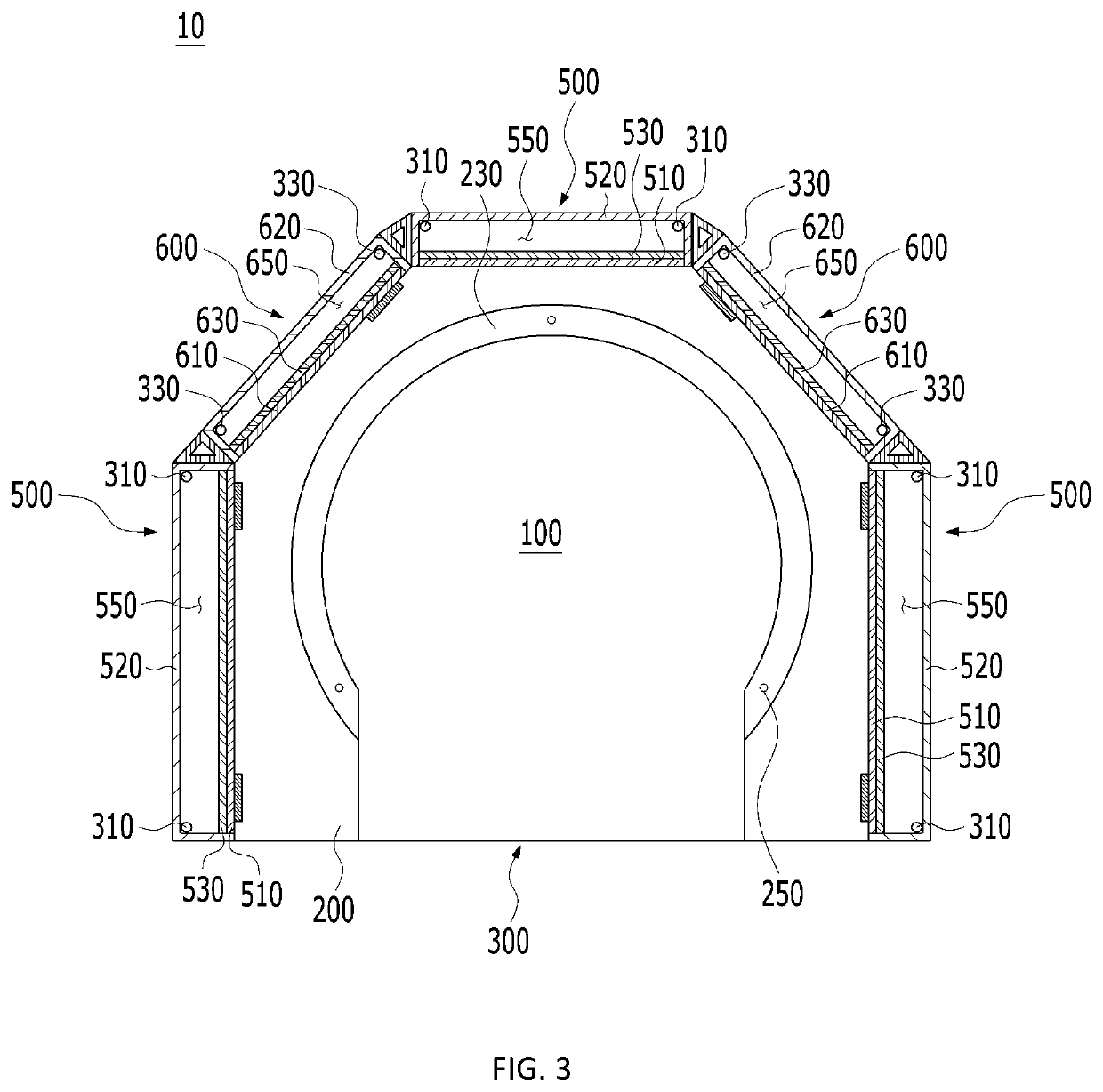
[0046]A wafer storage container according to the present invention includes: a storage chamber in which a wafer received through a front opening is stored; a support supporting the wafer stored in the storage chamber; a lower plate forming a lower surface of the wafer storage container; an upper plate forming an upper surface of the wafer storage container; an injection part injecting purge gas into the storage chamber; an exhaust part exhausting the purge gas injected into the storage chamber; and a blocking member configured to block at l...


PUM


Abstract

The present invention relates to a wafer storage container capable of removing fumes on a wafer or removing moisture therefrom by supplying purge gas to the wafer stored in a storage chamber. More particularly, the present invention relates to a wafer storage container capable of quickly blocking an injection hole and an exhaust hole and of preventing contaminants from flowing into a storage chamber upon the blocking of the exhaust hole.

Description

CROSS-REFERENCE TO RELATED APPLICATIONS[0001]The present specification is a U.S. National Stage of International Patent Application No. PCT / KR2018 / 003877 filed Apr. 2, 2018, the entire contents of which are incorporated herein by reference.TECHNICAL FIELD[0002]The present invention relates generally to a wafer storage container and, more particularly, to a wafer storage container capable of removing fumes on a wafer or removing moisture therefrom by supplying purge gas to the wafer stored in a storage chamber.BACKGROUND ART[0003]In general, semiconductor devices are manufactured by performing selection and repeating a series of unit processes on wafers such as deposition, polishing, photolithography, etching, ion implantation, cleaning, inspection, thermal treatment, etc. The wafers are transferred to a predetermined location required in each process to manufacture semiconductor devices.[0004]Such wafers require high precision processes and are stored in or transferred to and from a...

Claims


Application Information

Patent Timeline
Patent Type & Authority Patents(United States)
IPC IPC(8): H01L21/673
CPCH01L21/67393H01L21/67386H01L21/6732H01L21/6735H01L21/67389
Inventor WOO, BUM JE
Owner WOO BUM JE
Features
  • R&D
  • Intellectual Property
  • Life Sciences
  • Materials
  • Tech Scout
  • Unparalleled Data Quality
  • Higher Quality Content
  • 60% Fewer Hallucinations
Learn More