Oar apparatus having a pivoting oar blade

a technology of oar blades and oar blades, which is applied in the field of oars, can solve the problems of unresolved design flaws, prone to malfunction of self-feathering mechanisms involving hinges and springs, and the like of those taught, so as to facilitate smooth and low-friction rotation of shafts, facilitate reliable repeated rotation, and reduce static and kinetic friction coefficients

Active Publication Date: 2022-06-14
THE FIRST AMENDED & RESTATED HOLLEY TRUST AGREEMENT OF MARCH 7 2011 DATED JULY 26 2017
View PDF8 Cites 0 Cited by
  • Summary
  • Abstract
  • Description
  • Claims
  • Application Information

AI Technical Summary

Benefits of technology

[0008]To facilitate the ease of reliable repeated rotation of the shaft within the lumen of the sheath, a layer of lubricant may be disposed at the interface of the shaft and the lumen of the sheath to reduce the coefficients of static and kinetic friction therebetween. Alternatively, one or more bearings can be positioned within the lumen of the sheath to facilitate smooth and low-friction rotation of the shaft relative to the sheath.

Problems solved by technology

However, these designs have unresolved flaws.
Because the oar blades are configured to be submerged underwater for extended period of time complex self-feathering mechanisms involving hinges and springs—such as those taught in the prior art—are prone to malfunction.

Method used


Image

  • Oar apparatus having a pivoting oar blade
  • Oar apparatus having a pivoting oar blade
  • Oar apparatus having a pivoting oar blade

Examples


Embodiment Construction

[0024]In the following detailed description of the preferred embodiment, reference is made to the accompanying drawings, which form a part hereof, and within which specific embodiments are shown by way of illustration by which the invention may be practiced. It is to be understood that other embodiments may be utilized, and structural changes may be made without departing from the scope of the invention.

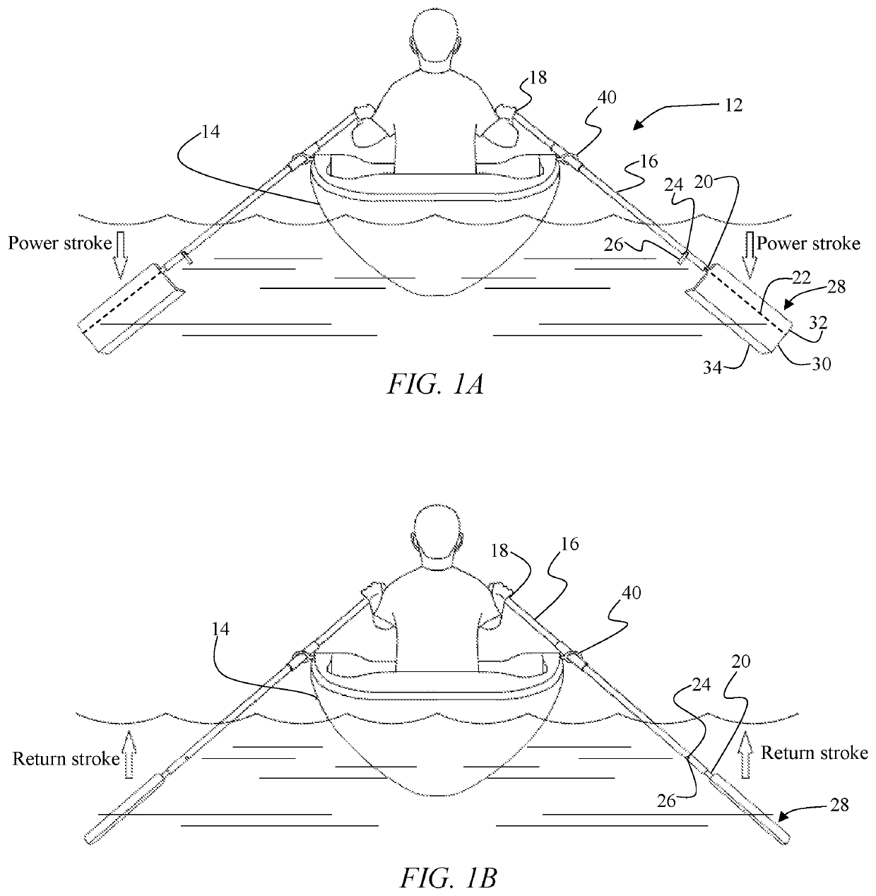
[0025]Referring to FIGS. 1A and 1B, an embodiment of the invention pertains to an oar apparatus 12 manually operated by a rower to propel a vessel 14 through the water. The oar apparatus 12 has a sheath 16. Sheath 16 may have a tubular body with an internal lumen. A handle 18 may be disposed on a proximal end of sheath 16 to enable the rower to comfortably hold and operate oar apparatus 12.

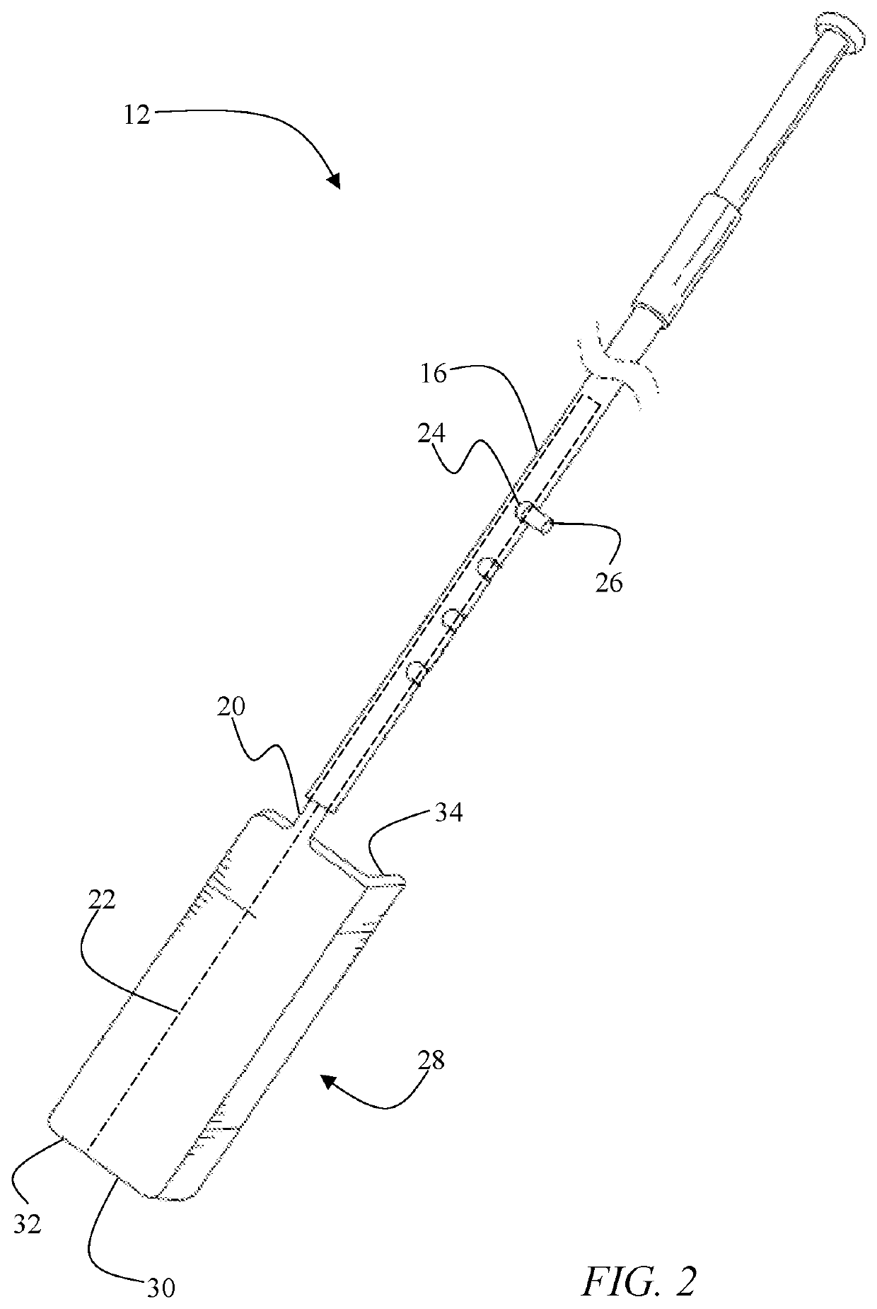
[0026]FIGS. 1A-1B and 2 depict that oar apparatus 12 has a shaft 20 coupled to sheath 16. Shaft 20 may have an elongated cylindrical body. A first end of shaft 20 resides within the lumen of sheath...


PUM


Abstract

An oar apparatus configured to remain submerged under water during the power stroke and the return stroke. The oar apparatus has a sheath and a shaft rotationally disposed within the sheath. An oar blade is affixed to the shaft, such that the oar blade is rotational relative to the sheath. The oar blade has a deployed orientation, in which the oar blade is substantially perpendicular to the movement direction of the vessel, and a feathered configuration, in which the oar blade is substantially parallel to the movement direction of the vessel. The oar blade is asymmetrical relative to the center axis of the shaft, such that resistance of the water exerted onto the oar blade creates a first moment urging the oar blade into the deployed orientation during the power stroke and a second moment urging the oar blade into the feathered orientation on the return stroke.

Description

BACKGROUND OF THE INVENTION1. Field of the Invention[0001]This invention relates to oars. More specifically, it relates to an oar apparatus having a pivoting oar blade configured to remain under water during the power stroke and the return stroke.2. Brief Description of the Related Art[0002]Water sports, such as kayaking and canoeing, have become a favorite pastime of many people. These water activities involve small vessels that are manually propelled using oars or paddles. Traditional oar designs require the user to submerge the blade of the oar into the water on the power stroke and remove the oar blade out of the water for the return stroke. Although this procedure may appear simple in principle, effective rowing with a traditional oar requires a fair amount of coordination, strength, and properly executed technique.[0003]In an attempt to overcome the disadvantages of the traditional oars, several self-feathering oar designs have been introduced in the past that enable the oar b...

Claims


Application Information

Patent Timeline
Patent Type & Authority Patents(United States)
IPC IPC(8): B63H16/04B63H16/073
CPCB63H16/04B63H16/073
Inventor HOLLEY, WILLIAM E.
Owner THE FIRST AMENDED & RESTATED HOLLEY TRUST AGREEMENT OF MARCH 7 2011 DATED JULY 26 2017
Why Eureka
Try Eureka