Thin film metallic glass coated needle

a technology of metallic glass and coated needles, applied in the direction of needles, sewing machine elements, surgery, etc., can solve the problems of inability to meet the product requirements of certain industries, process interruptions, and increased friction between needles and skin, so as to reduce surface roughness and coefficient of friction, and increase the hardness of the needle head. , the effect of promoting the durability of the needl

Active Publication Date: 2017-12-12
NAT TAIWAN UNIV OF SCI & TECH
View PDF12 Cites 0 Cited by
  • Summary
  • Abstract
  • Description
  • Claims
  • Application Information

AI Technical Summary

Benefits of technology

[0012]The instant disclosure provides a thin film metallic glass coating on a surface of a needle body and a surface of a needle head so as to reduce surface roughness and coefficient of friction. The hardness of the needle head can be increased by coating with thin film metallic glass. The thin film metallic glass is less likely to stick or be stuck on other materials. The durability of the needle is greatly promoted.
[0013]According to some embodiments of the instant disclosure, a thin film metallic glass coated needle includes a needle body, a needle head and a thin film metallic glass in amorphous structure and formed on a surface of the needle head and a surface of the needle body to reduce the surface energy, coefficient of friction, surface roughness, and simultaneously increase the hardness of the needle head.

Problems solved by technology

However, conventional metallic materials are mostly crystalline with limited malleability and therefore fail to satisfy product requirement in certain industry.
Although the size of tip and glue material may be different, the difficulties encountered are usually related to the residue glue on the tip surface, leading to process interruption for clearance.
However, in aesthetic or plastic surgery, the needle may be repeatedly used to tens or hundreds of times. After the heavy use, the friction between needle and skin may increase because lubricant dries out.
Clinically, when using stitching needle to handle the wound, the duration and area may be long and broad, such that the needle head may become blunt, causing difficulty in operation.
Although the coefficient of friction can be reduced and so as the friction resistance, the overall thickness can reach to 1000 nm, and the wound can be too large to recover.

Method used


Image

  • Thin film metallic glass coated needle
  • Thin film metallic glass coated needle
  • Thin film metallic glass coated needle

Examples


Embodiment Construction

[0022]Reference will now be made in detail to the present embodiments of the invention, examples of which are illustrated in the accompanying drawings. Wherever possible, the same reference numbers are used in the drawings and the description to refer to the same or like parts.

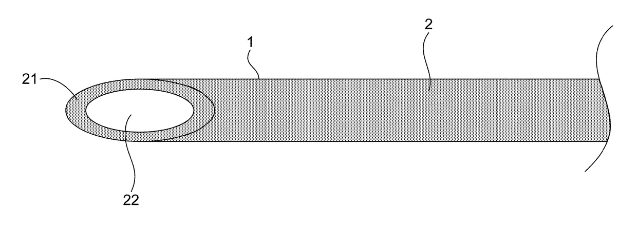
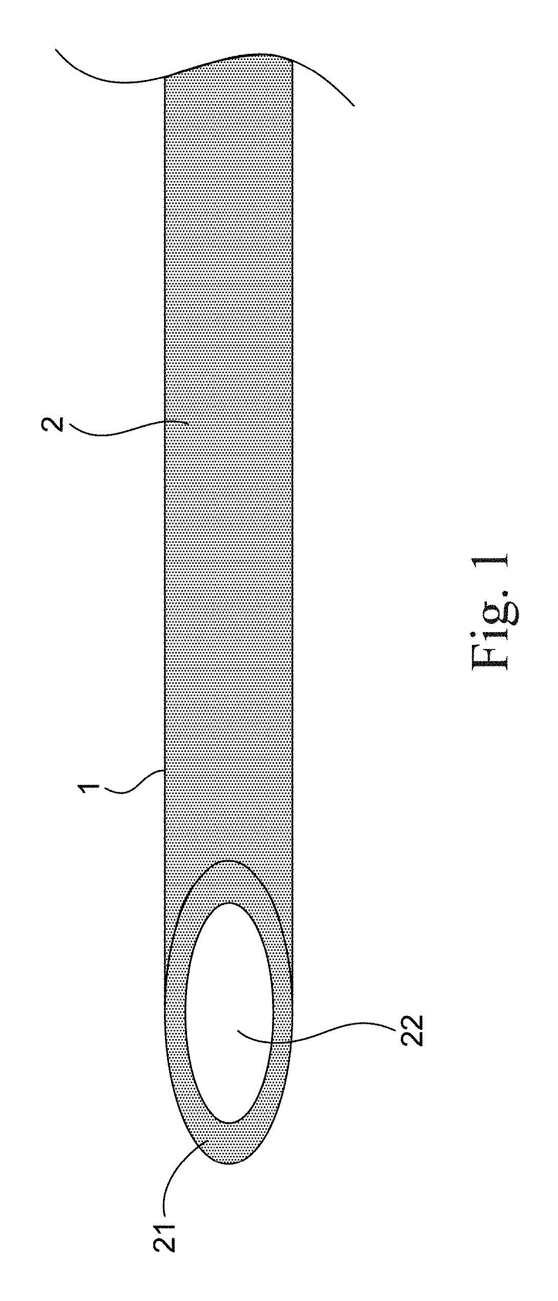
[0023]Please refer to FIG. 1, showing a thin film metallic glass coated needle in accordance with an embodiment of the instant disclosure. As shown in FIG. 1, the thin film metallic glass (TFMG) 1 is an amorphous material and is formed on a surface of the needle body 2 and a surface of the needle head 21 of the needle body 2 so as to reduce the interfacial friction and surface roughness and increase the hardness of the needle head. In addition, in another embodiment of the instant disclosure, the needle body 2 has a needle tube 22. The inner surface of the needle tube 22 is coated with the thin film metallic glass 1. The thin film metallic glass 1 is a titanium-based thin film metallic glass. The thin film met...


PUM

PropertyMeasurementUnit
surface energyaaaaaaaaaa
thicknessaaaaaaaaaa
thicknessaaaaaaaaaa

Abstract

A thin film metallic glass coated needle includes a needle body, a needle head and a thin film metallic glass in amorphous structure and formed on a surface of the needle head and a surface of the needle body to reduce a surface energy and coefficient of friction. The thin film metallic glass is a titanium based comprising 35-45 at % titanium, 5-15 at % zirconium, 32-42 at % copper, 1-11 at % niobium and 2-12 at % cobalt.

Description

RELATED APPLICATIONS[0001]This application claims priority to Taiwan Application Serial Number 104115493, filed May 15, 2015, which is herein incorporated by reference.BACKGROUND[0002]Field of Invention[0003]The present invention relates to a thin film metallic glass. More particularly, the present invention relates to a thin film metallic glass for coating.[0004]Description of Related Art[0005]Metal, ceramic and polymer materials are widely used in our daily life. The implementation of metallic materials occupies the highest percentage. In comparison with polymer or composite materials, metallic materials have better physical resistance. Furthermore, metallic materials have longer researching history, and therefore the technique of associated fields is more mature and well developed. They can be found everywhere in a variety of products.[0006]Common metallic material, for example, nano titanium aluminium nitride film, which shows high hardness, is used to improve the wear resistanc...

Claims


Application Information

Patent Timeline
Patent Type & Authority Patents(United States)
IPC IPC(8): B32B15/00D05B85/12A61B17/06A61M5/32A61B17/00
CPCD05B85/12A61B17/06066A61M5/329A61B2017/00526A61B2017/0084C22C45/001
Inventor CHU, JINNTANATSUGU, YUSUKEYU, CHIA-CHILI, CHIA-LIN
Owner NAT TAIWAN UNIV OF SCI & TECH
Why Eureka
Try Eureka