Exhaled breath condensate collection device and a kit of parts therefor

a technology of exhaled breath and collection device, which is applied in the field of diagnostic recording/measuring, laboratory glassware, applications, etc., can solve the problems of affecting the results of any subsequent analysis, affecting the quality of exhaled breath, so as to prevent the contamination of the collection vessel, reduce the contamination of the sample, and facilitate the movement.

Active Publication Date: 2022-06-28
NORTHUMBRIA UNIVERSITY
View PDF19 Cites 0 Cited by
  • Summary
  • Abstract
  • Description
  • Claims
  • Application Information

AI Technical Summary

Benefits of technology

[0008]Thus, contamination of the sample is substantially reduced by providing the collection vessel in a sealed configuration prior to insertion into the device, and resealing the collection vessel into the sample containment configuration after sample collection but before the collection vessel is fully removed from the device. This configuration also substantially prevents loss of the sample from the collection vessel.
[0009]One or more parts of the kit of parts may be configured and / or operable such that the collection vessel is caused to be unsealed into the sample collection configuration on or following insertion of the collection vessel into the device. Thus, the collection vessel is only unsealed on or following insertion of the collection vessel into the device, which substantially prevents contamination of the collection vessel from contaminants outside the device.
[0024]The resealing mechanism may be biased towards a sealed configuration. The collection vessel and one or more other parts of the device may be configured to keep the resealing mechanism out of the sealed configuration when inserted into the device for sample collection and allow the resealing mechanism to return to the sealed configuration as the collection vessel is removed from the device. Thus, the collection vessel is sealed before being fully removed from the device, substantially preventing sample loss or contamination.
[0036]The kit of parts may further comprise a temperature sensor for the mouthpiece temperature control component or for the cooling component. The temperature sensor may be custom, integrated, off-the-shelf or chaotic structure, electronic, solid state, electromagnetic, optical, thermochromatic, or electric, with the option of sensor-centric and inter-sensor communication and processing capabilities in real time. There will be at least one temperature sensor but preferably more, standby, active redundant, located at uniform or non-uniform intervals and spacing in all components to enable reliable, high efficiency thermal regulation.
[0041]The cooling elements may comprise plates, straight, flat, angled, geometrically organised, curved, flanged or finned with / without millimetre, micrometer or nanometer features such as tubes, channels pores, fins or other custom or chaotic designs that achieve high thermal conductivity through maximisation of surface area, flow, conductivity or radiation that enables accelerated, high efficiency thermodynamic exchange.
[0044]The different components may rely on interference fit on entry at ambient temperature to enable easier electrical, mechanical, electromechanical or manual means collection vessel extraction from the non-disposable housing upon actuation completion.

Problems solved by technology

During development, the inventor has realised that collected exhaled breath condensate using the device described in U.S. Pat. No. 8,491,494 is susceptible to contamination when the mouthpiece is removed from the collection vessel because a separate sealing cap is only applied to the collection vessel after removal of the mouthpiece.
In this situation, contaminants may enter the collection vessel, possibly distorting the results of any subsequent analysis.
Furthermore, the collection vessel may heat up between collection and sealing, resulting in evaporation of some of the collected exhaled breath condensate.

Method used


Image

  • Exhaled breath condensate collection device and a kit of parts therefor
  • Exhaled breath condensate collection device and a kit of parts therefor
  • Exhaled breath condensate collection device and a kit of parts therefor

Examples


Embodiment Construction

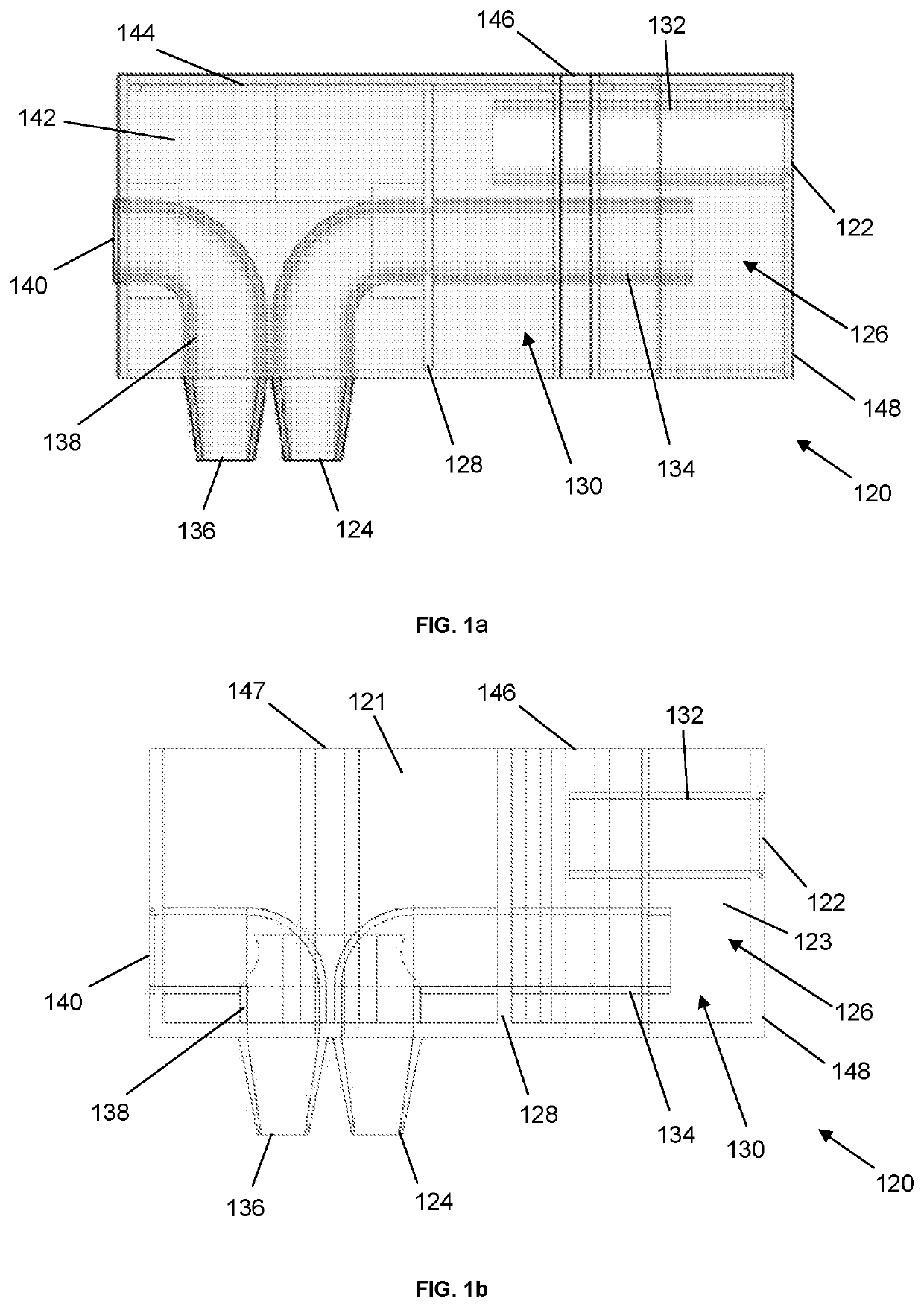
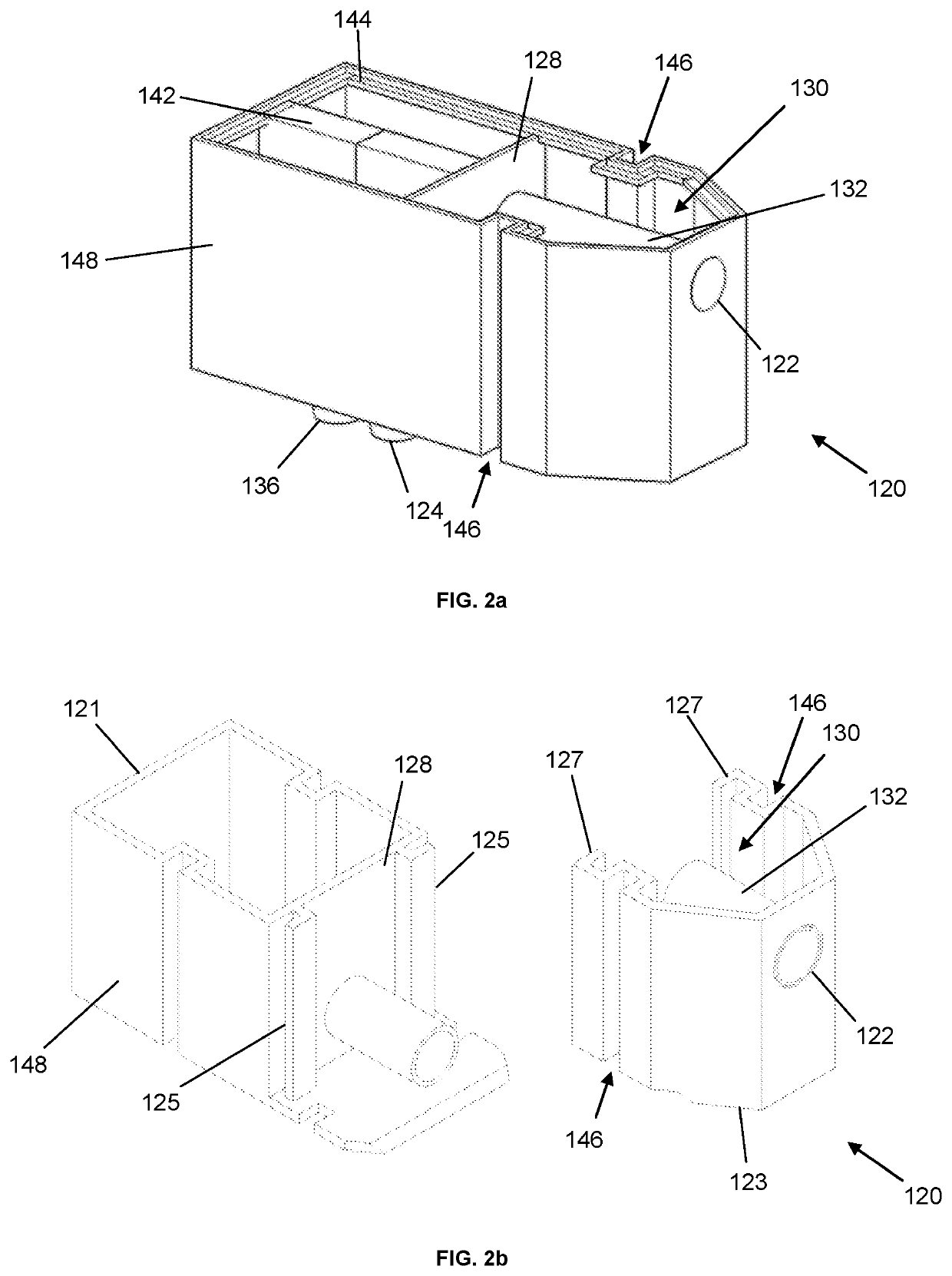
[0075]FIG. 1a is a diagram showing a mouthpiece inner component 120 of a mouthpiece module 100 in accordance with an embodiment of the present invention. FIG. 1a is provided in a semi-transparent view whereby to illustrate internal details of the mouthpiece inner component 120. FIG. 2a is an isometric view of the mouthpiece inner component 120 of FIG. 1a. FIG. 2a does not exhibit the same semi-transparent nature as FIG. 1a, whereby to more clearly illustrate the configuration of the mouthpiece inner component 120. The mouthpiece inner component 120 has defined therein a mouthpiece breath inlet port 122 configured to receive exhaled breath from a subject and a mouthpiece breath outlet port 124 arranged to be in fluid communication with the mouthpiece breath inlet port 122 to form a breath passageway and to output exhaled breath out of the mouthpiece module 100. The mouthpiece inner component 120 further comprises a saliva trap 126 in a mouthpiece first chamber 130 formed in the breat...


PUM


Abstract

There is provided a kit of parts for an exhaled breath condensate collection device. The kit comprises a mouthpiece module (100) comprising a breath passageway defined in the mouthpiece module (100) providing fluid conduction from a mouthpiece breath inlet port (122) for receiving exhaled breath to a mouthpiece breath outlet port (124) in use. The kit further comprises a collection vessel (300) for insertion into the device for cooling in use. The collection vessel (300) defines a sealed and resealable chamber for collecting exhaled breath condensate in use. The collection vessel has a vessel breath inlet (326) for admitting exhaled breath into the chamber. The kit of parts is configured such that the collection vessel (300) is: insertable into the device into an sample collection configuration in which the vessel breath inlet (326) is unsealed and in fluid communication with the mouthpiece breath outlet port (124) of the mouthpiece module (100); and removable from the device in a sample containment configuration in which the collection vessel chamber is resealed. One or more parts of the kit of parts is configured and / or operable such that the collection vessel (300) is caused to be resealed into the sample containment configuration after sample collection before the collection vessel (300) is fully removed from the device.

Description

CROSS-REFERENCE TO RELATED APPLICATIONS[0001]This application is a U.S. National Stage application of International Application Serial No. PCT / GB2017 / 050627, filed Mar. 8, 2017, which claims priority to Great Britain Application Serial No. GB 1604011.5, filed Mar. 8, 2016, each of which are incorporated by reference herein in their entirety[0002]This invention relates to an exhaled breath condensate collection device, a kit of parts for the exhaled breath condensate collection device and a method of exhaled breath condensate collection.BACKGROUND[0003]Exhaled breath vapour typically contains a mixture of different components, which can give an indication of airway disease and physiology for a subject. It is known to extract these components by passing exhaled breath directly through a cooled collection vessel in order to initiate condensing of many of the constituent parts of the exhaled breath vapour. The exhaled breath condensate remains in the collection vessel, whilst any remain...

Claims


Application Information

Patent Timeline
Patent Type & Authority Patents(United States)
IPC IPC(8): A61B5/097A61B5/08A61M39/06A61M39/22B01L3/00A61B10/00B65D47/26
CPCA61B5/097A61M39/06A61M39/22B01L3/5021A61B5/082A61B10/0096A61B2010/0087B65D47/26A61B2560/0443
Inventor MOSCHOS, STERGHIOS A.KALE, IZZET
Owner NORTHUMBRIA UNIVERSITY
Why Eureka
Try Eureka