Oscillating axle for a lifting device, lifting device comprising such an axle and control method

a technology of oscillating axle and lifting device, which is applied in the direction of lifting device, lifting frame, safety device for lifting equipment, etc., can solve the problems of machine risking overturning and wheel losing contact with the ground

Active Publication Date: 2022-07-05
HAULOTTE GROUP
View PDF13 Cites 4 Cited by
  • Summary
  • Abstract
  • Description
  • Claims
  • Application Information

AI Technical Summary

Problems solved by technology

In the event of an undetected failure of one of these solenoid valves, a jack may remain blocked in the ground travel configuration, causing a wheel to lose contact with the ground.
In a lifting phase, the machine risks overturning if the load on the platform or the machine's center of gravity moves towards the wheel that is not supported on the ground.

Method used


Image

  • Oscillating axle for a lifting device, lifting device comprising such an axle and control method
  • Oscillating axle for a lifting device, lifting device comprising such an axle and control method
  • Oscillating axle for a lifting device, lifting device comprising such an axle and control method

Examples


Embodiment Construction

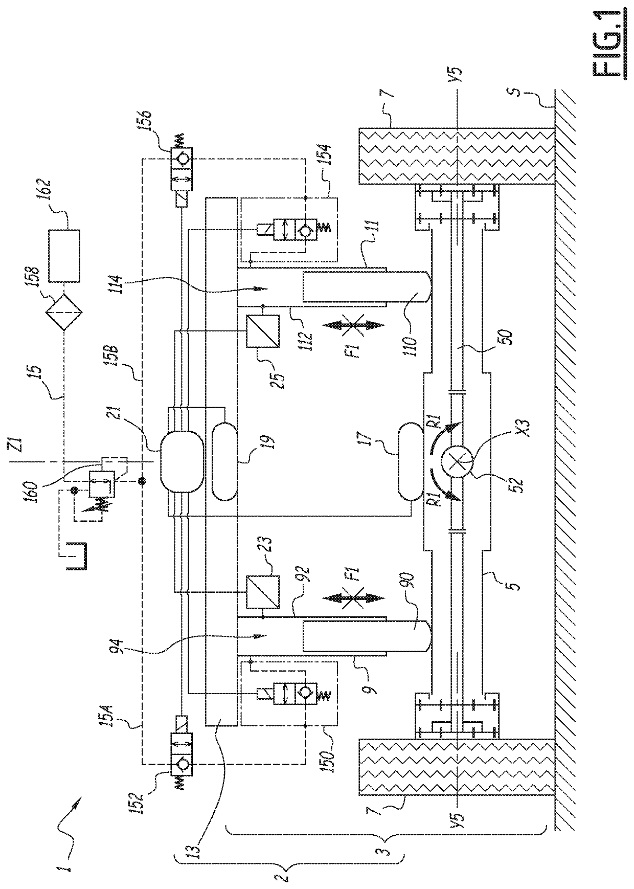
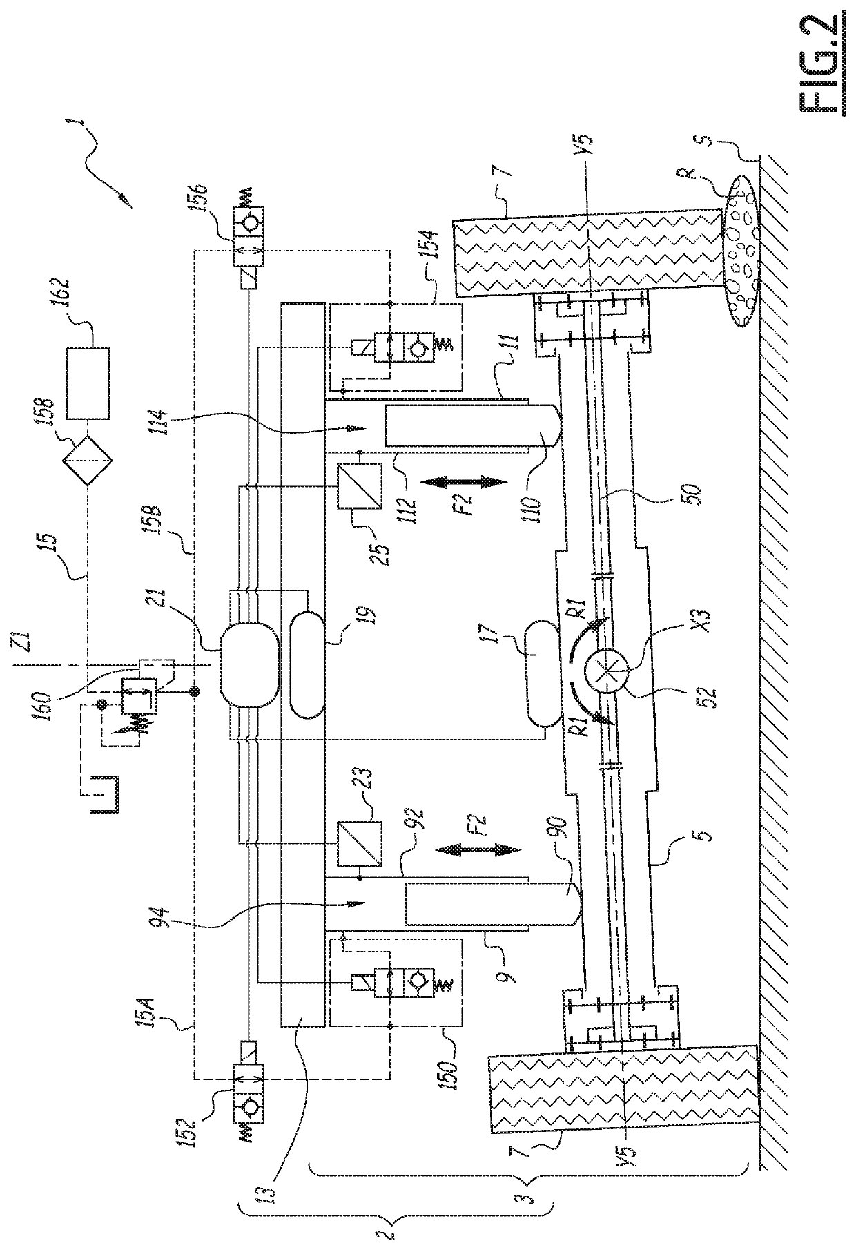
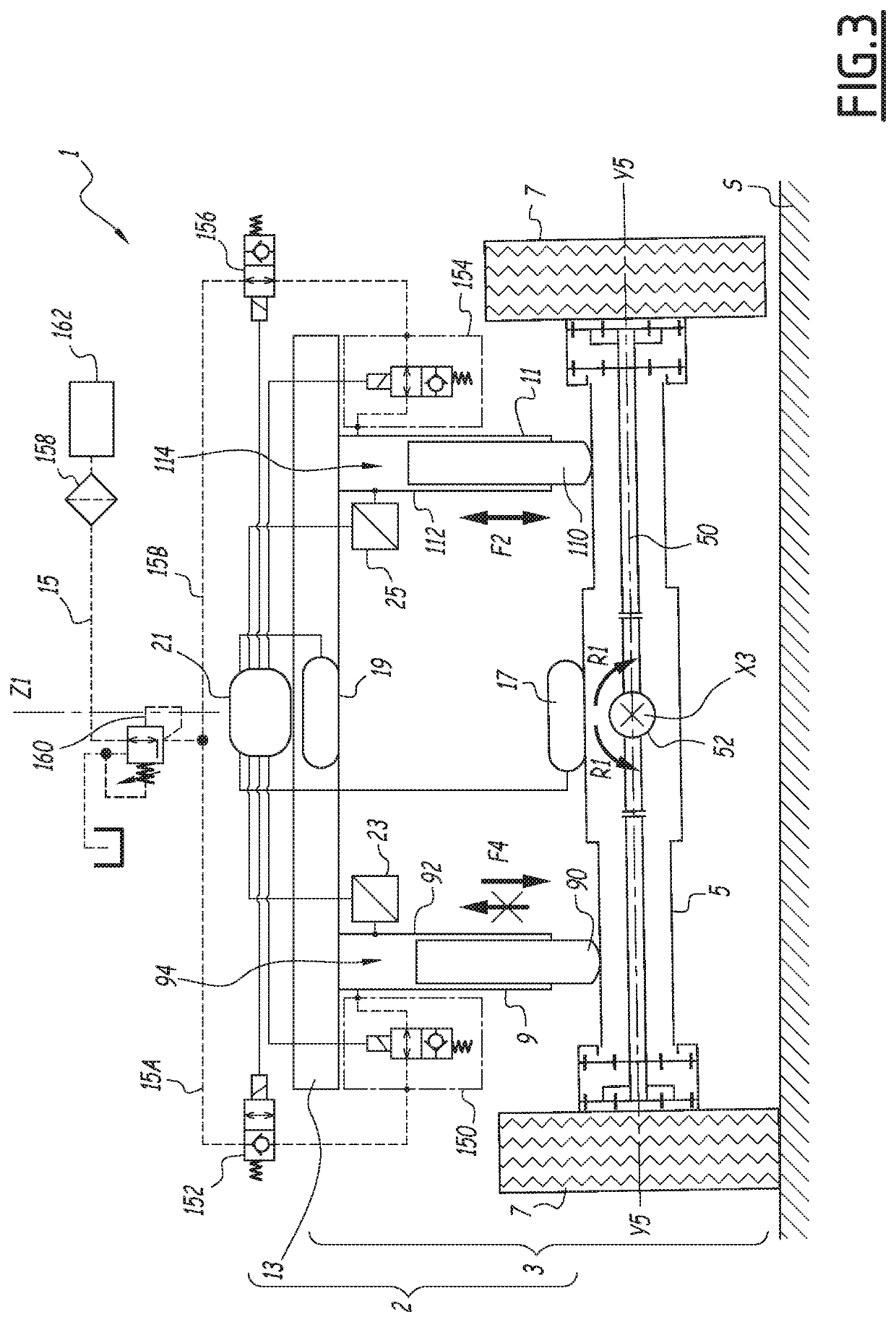
[0034]FIGS. 1 to 3 show a lifting device 1, such as a lifting platform, comprising a lower part comprising a chassis 2 and members connecting with the ground, and a lifting structure (not shown) supporting a platform (not shown). The lifting structure may be of the type comprising telescopic and articulated sections, or else of the “scissor” type.

[0035]In a conventional example, the lower part comprises four members connecting with the ground in the form of the wheels 7. The chassis 2 comprises a fixed part 13 and at least one oscillating axle, one of the latter of which is shown in FIG. 1 with the reference 3. The wheels 7 are mounted two by two on the axles. The fixed part 13 is fixed relative to a vertical axis Z1 of the lifting device 1.

[0036]The oscillating axle 3 comprises a bridge 5 having, at each of its ends, a wheel 7. The bridge 5 is a mechanical structure supporting the wheels 7, which includes a transmission shaft 50 to rotate the wheels 7 and which is also capable of m...


PUM


Abstract

This oscillating axle (3) for a lifting device (1) comprises an axle bridge (5) at the ends of which are mounted two ground connection members (7), an oscillation axis (X3), a left jack (9) and a right jack (11), each jack (9, 11) having a rod (90, 110) in contact with the bridge (5) and a body (92, 112) fixed on a fixed part (13) of a chassis (2) of the lifting device (1), the body (92, 112) forming a chamber (94, 114) in which the rod (90, 110) moves. The axle comprises a hydraulic circuit (15) interconnecting the chambers (92, 112) of the left (9) and right (11) jacks, in which a fluid is present at a given pressure, making it possible to press the rods (90, 110) of the left jack (9) and of the right jack (11) against the bridge (5), and at least one solenoid valve (150, 152) on a branch (15A) of the hydraulic circuit (15) connected to the chamber (94) of the left jack (9), and at least one solenoid valve (154, 156) on a branch (15B) of the hydraulic circuit (15) connected to the chamber (114) of the right jack (11), wherein each of these solenoid valves (150, 152, 154, 156) may be positioned in an open position, in which fluid may flow freely, and a closed position, in which the fluid is trapped in the chamber (94, 114) of the corresponding jack (9, 11). Each of the chambers (94, 114) of the left jack (9) and of the right jack (11) has a pressure sensor (23, 25) designed to measure the pressure of the fluid in each of the chambers (94, 114). Control means (21) are provided to detect a pressure in one of the chambers (94, 114) that is greater than a first threshold, and/or a differential between the pressures in each of the chambers (94, 114) that is greater than a second threshold, so as to detect the blocking of a solenoid valve (150, 152, 154, 156) in the closed position, and to initiate a safety procedure.

Description

[0001]This application claims priority to FR Patent Application No. 1909665 filed Sep. 3, 2019, the entire contents of each of which are hereby incorporated by reference.BACKGROUND OF THE INVENTIONField of the Invention[0002]The present invention relates to an oscillating axle for a lifting device, a lifting device comprising such an axle, as well as a method of controlling such a lifting device.Description of the Related Art[0003]Lifting devices such as aerial work platforms may be equipped with oscillating axles, in particular as described in EP 1 414 733 or CN 104528609, making it possible to maintain contact with the ground on uneven terrain in order to preserve the stability of the machine. These oscillating axles comprise a bridge on which are mounted a wheel at each end, and jacks connecting the vehicle chassis and the bridge. The jacks may be double-acting: wherein in the nacelle displacement configuration with the lifting structure lowered, the translation of the jack is fr...

Claims


Application Information

Patent Timeline
Patent Type & Authority Patents(United States)
IPC IPC(8): B60G17/056B60G9/02
CPCB60G17/0565B60G9/02B60G2200/326B60G2202/413B60G2204/421B60G2400/50B66F7/16B66F7/22B66F7/28B66F11/04B66F13/00B66F17/006B66F9/07586B60G2300/022B60G2200/322B60G2202/414B60G17/005B66F17/00B60G21/073B60G2400/51B60G2600/02B60G2800/80B60G2800/0124B60G17/0185B60G2600/044
Inventor SIMON, ALEXANDRECOGNET, RÉMY
Owner HAULOTTE GROUP
Why Eureka
Try Eureka