Supercharge Your Innovation With Domain-Expert AI Agents!

Monitoring system and power supply control method

a monitoring system and power supply technology, applied in the direction of safety/protection circuits, electric devices, transportation and packaging, etc., can solve the problems of charging efficiency, unexpected energy consumption and temperature rise, and the charging plate may be subject to moisture or even rus

Active Publication Date: 2022-07-05
CORETRONIC INTELLIGENT ROBOTICS CORP
View PDF24 Cites 0 Cited by
  • Summary
  • Abstract
  • Description
  • Claims
  • Application Information

AI Technical Summary

Benefits of technology

The invention makes a determination based on the electrical characteristic of whether there is a foreign object or other abnormal situations affecting the power supply of the drone or base station. It adjusts the charging mode and voltage accordingly to compensate for power supply loss caused by the abnormal situation and improve charging efficiency. This ensures that the drone can be fully charged even under abnormal conditions.

Problems solved by technology

However, because the charging device is usually placed outdoors, and a charging plate of the charging device is usually made of metal, the charging plate may be subject to moisture or even rust due to climate, or a foreign object may fall on the charging plate.
The foregoing situations affect the charging efficiency and cause problems including unexpected energy consumption and temperature rise.
In addition, the drone may be incompletely charged or unable to be fully charged within a fixed time.
As a result, the charging time needs to be extended, thereby affecting task execution frequency and efficiency.

Method used


Image

  • Monitoring system and power supply control method
  • Monitoring system and power supply control method
  • Monitoring system and power supply control method

Examples


Embodiment Construction

[0039]In the following detailed description of the preferred embodiments, reference is made to the accompanying drawings which form a part hereof, and in which are shown by way of illustration specific embodiments in which the invention may be practiced. In this regard, directional terminology, such as “top,”“bottom,”“front,”“back,” etc., is used with reference to the orientation of the Figure(s) being described. The components of the invention can be positioned in a number of different orientations. As such, the directional terminology is used for purposes of illustration and is in no way limiting. Unless limited otherwise, the terms “connected,”“coupled,” and “mounted” and variations thereof herein are used broadly and encompass direct and indirect connections, couplings, and mountings. Besides, the terminology “signal” may refer to as at least one current, voltage, charge, temperature, data, electromagnetic wave, or any other one or more signal.

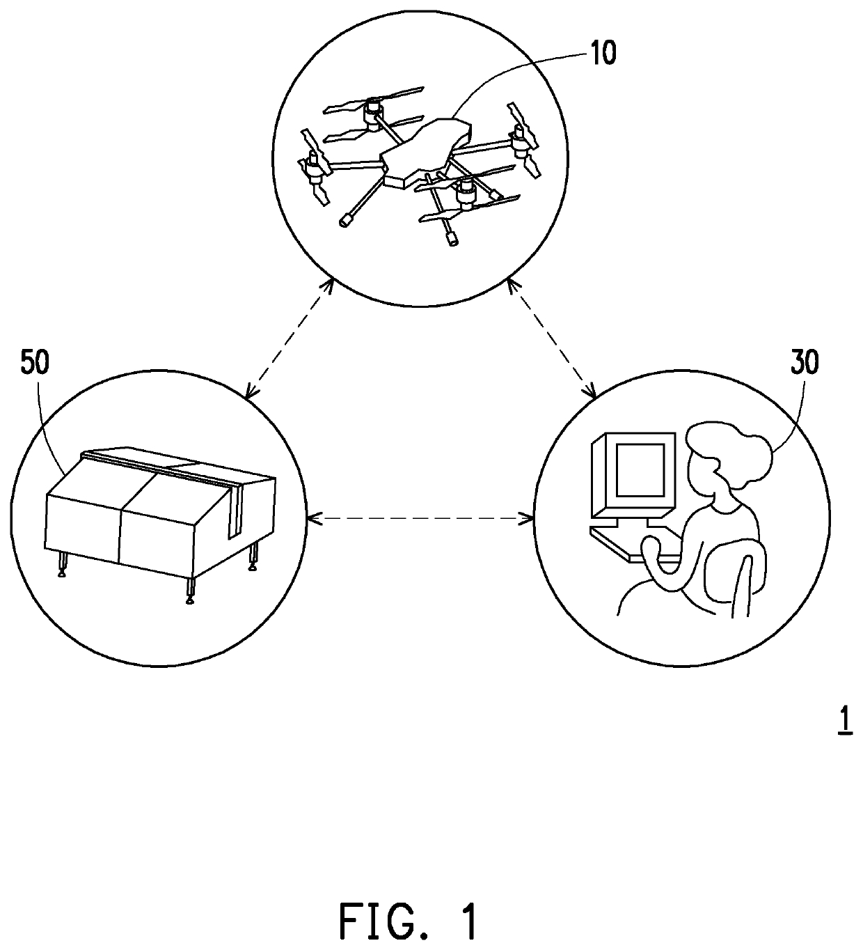
[0040]FIG. 1 is a schematic diagram...


PUM


Abstract

A power supply control method and a monitoring system configured to implement the power supply control method are provided. The monitoring system includes a base station, a drone, and a processor. The base station includes a charging device. The charging device includes a power supply connector and a power source coupled to the power supply connector and outputting electric power through the power supply connector. The drone includes a battery configured to provide electric power to the drone and a charging connector configured to connect the battery and the power supply connector. When the charging connector is connected to the power supply connector, the processor determines an abnormal situation on the power supply connector or the drone according to an electrical characteristic during charging the battery by the power source. The abnormal situation is associated with a foreign object formed on the power supply connector or the drone.

Description

CROSS-REFERENCE TO RELATED APPLICATION[0001]This application claims the priority benefit of Taiwan patent application serial no. 108145007, filed on Dec. 10, 2019. The entirety of the above-mentioned patent application is hereby incorporated by reference herein and made a part of this specification.BACKGROUND OF THE INVENTIONField of the Invention[0002]The invention relates to a monitoring technology for a drone, and in particular, to a monitoring system and a power supply control method for a drone.Description of Related Art[0003]A monitoring technology is applied by various industries to monitor devices, buildings, or other assets. Research units may monitor animals or ecology, and government agencies may monitor roads, parks, or entrances and exits. In order to eliminate human factors, automatic monitoring is available today, and automatic monitoring devices may be arranged at specific locations for environmental monitoring. The automatic monitoring device may include a drone and...

Claims


Application Information

Patent Timeline
Patent Type & Authority Patents(United States)
IPC IPC(8): H02J7/00B60L53/16B60L53/62B64C39/02
CPCB60L53/16B60L53/62B64C39/024H02J7/0032H02J7/0044H02J7/0047H02J7/007182B60L3/0046B60L2250/10B60L2240/547B60L53/66B60L53/14B64F3/00H02J7/0036H02J2310/10Y02T10/70B64U50/30B64U50/37B64U2201/20
Inventor LEE, CHENG-SHENTSENG, CHIH-NENGKO, KUAN-CHOU
Owner CORETRONIC INTELLIGENT ROBOTICS CORP
Features
  • R&D
  • Intellectual Property
  • Life Sciences
  • Materials
  • Tech Scout
  • Unparalleled Data Quality
  • Higher Quality Content
  • 60% Fewer Hallucinations
Learn More