
Heating system for fiber-reinforced thermoplastic feedstock and workpiece

Active Publication Date: 2022-07-12
AREVO INC
View PDF10 Cites 0 Cited by
  • Summary
  • Abstract
  • Description
  • Claims
  • Application Information

AI Technical Summary

Benefits of technology

The second embodiment of this patent involves using four laser beams to address specific problems when heating the feedstock and workpiece during a deposition process. This allows the laser beams to work together and fine-tune the temperature of the feedstock and workpiece before deposition. The use of four laser beams is cost-effective and allows for better temperature control and higher deposition rates. The use of one optical cable to carry all the laser beams simplifies the overall system design, making the deposition head lighter and more compact. Overall, the second embodiment provides improved efficiency and control during the deposition process.

Problems solved by technology

If the temperature of either is too low, then the weld will be defective, and if the temperature of either is too high, then it could burn or melt.
In practice, however, it fails to produce quality welds, and on close examination, the reason why is clear: the task of heating the workpiece is, in general, far more complex and variable than the task of heating the feedstock.

Method used


Image

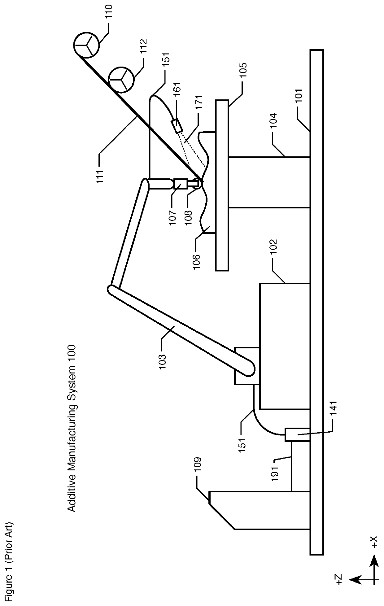
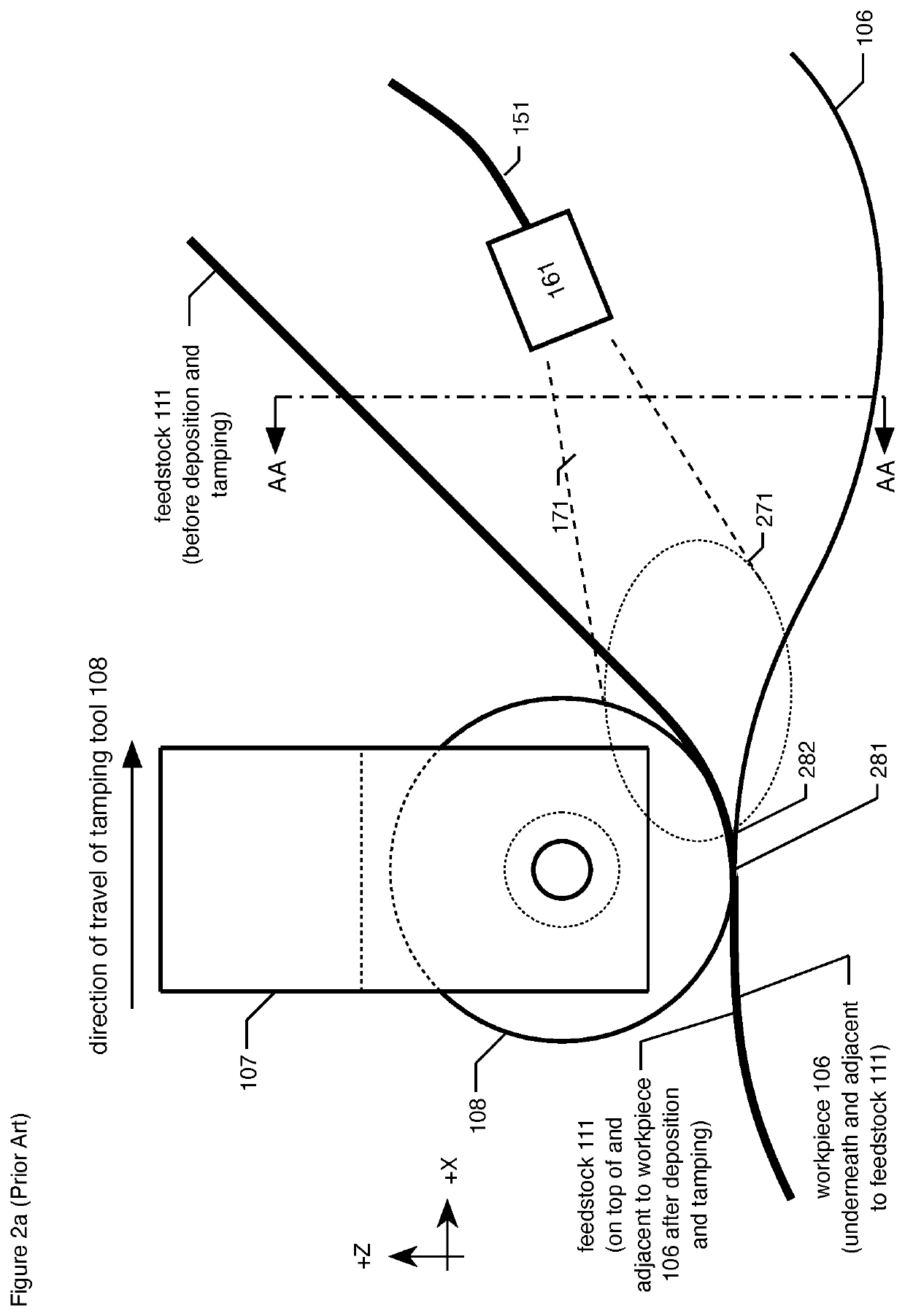
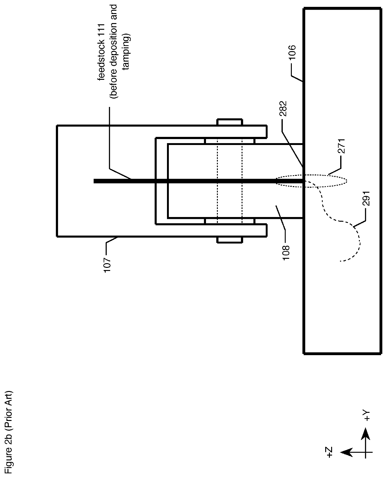
  • Heating system for fiber-reinforced thermoplastic feedstock and workpiece
  • Heating system for fiber-reinforced thermoplastic feedstock and workpiece
  • Heating system for fiber-reinforced thermoplastic feedstock and workpiece

Examples


Embodiment Construction

[0092]FIG. 4 depicts an illustration of additive manufacturing system 400 in accordance with the first illustrative embodiment of the present invention. Additive manufacturing system 400 fabricates an article of manufacture by successively depositing segments of fiber-reinforced thermoplastic feedstock (e.g., filament, tape, etc.) onto a workpiece until the article of manufacture is complete.

[0093]Additive manufacturing system 400 comprises: platform 401, robot mount 402, robot 403, build plate support 404, build plate 405, workpiece 406, deposition head 407, tamping tool 408, controller 409, feedstock reel 410, feedstock 411, accumulator 412, force gauge 413, sensor array 415, feedstock laser 441, workpiece laser 442, optical cable 451, optical cable 452, sensor cable 454, optical instrument 461, optical instrument 462, laser beam 471, laser beam 472, feedstock laser control cable 491, and workpiece laser control cable 492, interrelated as shown.

[0094]FIG. 5a depicts a close-up of ...


PUM

PropertyMeasurementUnit
Temperatureaaaaaaaaaa
Angleaaaaaaaaaa
Wavelengthaaaaaaaaaa

Abstract

An additive manufacturing system is disclosed that comprises two or more lasers for precisely heating a fiber-reinforced thermoplastic feedstock and a fiber-reinforced thermoplastic workpiece in preparation for depositing and tamping the feedstock onto the workpiece. The system employs feedforward, a variety of sensors, and feedback to ensure that the feedstock and workpiece are properly heated.

Description

CROSS-REFERENCE TO RELATED APPLICATIONS[0001]The following are hereby incorporated by reference:[0002](i) U.S. Pat. No. 10,076,870, entitled “Filament Guide,” issued on Sep. 18, 2018; and[0003](ii) U.S. patent application Ser. No. 15 / 959,213, entitled “Variable-Contour Compaction Press,” filed on Apr. 21, 2018; and[0004](iii) U.S. patent application Ser. No. 15 / 959,214, entitled “Variable-Contour Compaction Roller,” filed on Apr. 21, 2018; and[0005](iv) U.S. patent application Ser. No. 15 / 959,215, entitled “Self-Cleaning Variable-Contour Compaction Press,” filed on Apr. 21, 2018; and[0006](v) U.S. patent application Ser. No. 16 / 023,197, entitled “Filament Cutter,” filed on Jun. 29, 2018; and[0007](vi) U.S. patent application Ser. No. 16 / 023,210, entitled “Filament Accumulator or Tensioning Assembly,” filed Jun. 29, 2018; and[0008](vii) U.S. patent application Ser. No. 16 / 690,765, entitled “Heater for Thermoplastic Filament and Workpiece,” filed Nov. 21, 2019; and[0009](viii) U.S. pa...

Claims


Application Information

Patent Timeline
IPC IPC(8): B29C64/141B33Y10/00B29C64/393B23K26/00B23K26/03B23K26/06B23K26/08B23K26/14B23K26/342B33Y50/02B33Y70/00B33Y30/00B29K101/12B29K307/04
CPCB29C64/141B23K26/0006B23K26/0093B23K26/034B23K26/0608B23K26/0626B23K26/0869B23K26/1464B23K26/342B29C64/393B33Y10/00B33Y50/02B33Y70/00B29K2101/12B29K2307/04B33Y30/00B23K26/0884B23K26/14B33Y70/10B29C64/218B29C64/295B29C70/38B29C64/118B29C2035/0838B29C35/0805B29C35/0266B29C35/0288
Inventor AUGUST, ZACHARY AARONBHEDA, HEMANTTREYGER, LEONID MICHAEL
Owner AREVO INC
Learn More